Category: Hardware

  • Made in Japan. Forever.

    “Made in Japan” — a label so rarely seen on electronic equipment today.

    But there was a time.

    That time was 70 years ago.

    That time is Now.

    Presenting the Kikusui MC-120 Oscilloclock!

    In 2025, ~Brian~ reached out to commission an Oscilloclock build. He had just 3 requirements:

    1. He wanted a custom conversion of an original vintage device.
    2. The device should have a large screen — at least 4″ diameter.
    3. The finished clock should include the Metropolis theme feature.

    We prepared an exclusive catalogue with select devices in our stock that would meet the large-screen requirement.

    ~Brian~ immediately spotted the model he wanted!

    It seems the finish of this unit reminded him of military devices his grandfather had once owned. Well, your senior Oscilloclock engineer certainly knows the influence a grandfather can have. A great choice, for all the right reasons!

    Fast forward to May 2026 — and the labour of love was complete!

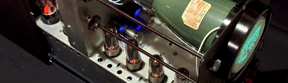
    Oh, my! Just look at those internals!

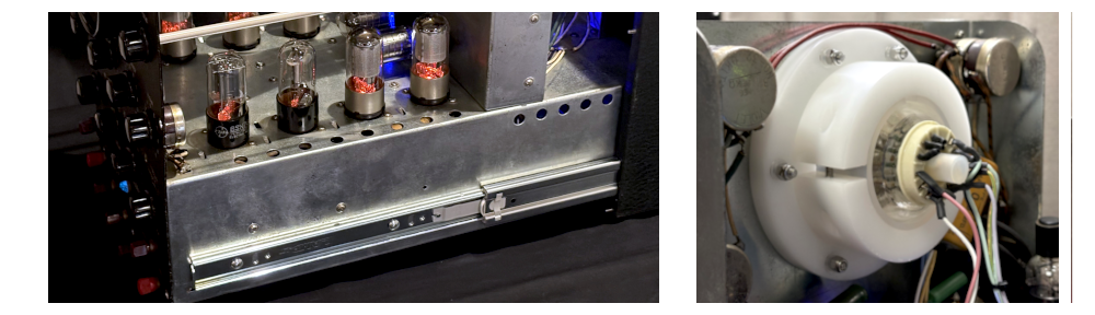
    We discovered at an early stage that the MC-120’s chassis slides out from the case relatively easily. Could we reduce friction enough that ~Brian~ could easily pull the unit open any time he wanted to gaze at the internals?

    ABSOLUTELY we could, and we did!

    But we took it one step further, by installing LED lighting into the tubes — simulating the look and feel of the original ‘scope in actual operation!

    Metropolis marks its 100th anniversary

    True to ~Brian’s~ every desire, his clock features the Metropolis themed screens, in addition to the the standard screens always available by default.

    This is perfect timing(!), as 2026 marks the 100th anniversary of the marvelous Metropolis movie by Fritz Lang!

    Screens are kept simple, but they bring a lot of pleasure!

    Latched on to Panels

    Avid readers may remember that we LOVE oscilloscopes that have panels. Especially those with latches. Check out our posts here, here, and here! We can’t resist playing with them, and we are absolutely not alone in this fetish.

    Well, this MC-120 also has a lovely latch panel in the rear. We’re not using it for anything. But look carefully! You can just see one of the LED-lit tubes inside…

    Wave for the camera!

    How do Oscilloclocks keep accurate time? We’ve written a full treatise before about the various options available. For the MC-120, we chose to install a custom Oscilloclock Wave board enabling NTP time synchronization over WiFi.

    This board has been designed specifically to replace the no-longer-necessary fuse box in the rear of the scope:

    Wait – reduce Weight!

    The Kikusui MC-120 in its original form weighed at least 20kg (45 lbs). ~Brian~ accepted our pragmatic suggestion to strip out the original power transformer and choke coil, bringing the weight of the entire unit down significantly.

    This weight loss helped greatly to reduce force required to pull out the chassis. But equally importantly, it halved the shipping costs!

    During the build, we also stripped out a number of other components. But don’t worry, most will not go to waste. Tube amp enthusiasts love transformers!!

    Hang on, where’s all the circuitry??

    ~Brian~ wished to retain the orginal looks above the chassis, so we mounted all Oscilloclock circuitry underneath!


    Like what you see?

    Actually, we hope you don’t like this specific Kikusui MC-120 too much, because it’s unlikely that we will ever come across another one! But never fear; we have other devices aplenty. We must have something special for you. And we can do some special things with it. Just let us know your ideas.

  • What’s up, Doc?

    Let me introduce [Howard]. He loves electronics, has a bunch of old scopes, is obsessed with time accuracy, and happens to be a retired medical doctor.

    What do you give a chap like Howard for his birthday?

    Well, his loving son [Nick] had the answer! He gave his dad the ultimate gift – an Oscilloclock Exo 3KP1 with a custom medical-themed animation!

    Hong Kong connection

    [Nick] first reached out in February to check out his options. He explained that the family was spread across continents, but would be uniting in Hong Kong for the big birthday event, in June. Four months away!

    Could Oscilloclock deliver something glorious and mesmerising for his dad – but in time, and within budget constraints?

    Yes and yes!

    The lab just happened to have a set of fully assembled, older-revision boards just begging for love and attention. And also in stock was a beautiful new cast acrylic Exo case and CRT ring set — with some slight imperfections.

    By using these components, we could reduce the time needed to craft the device — and offer a substantial discount to boot!

    The clock was ready and shipped a week ahead of time – making sure [Howard] would not go disappointed on his big day.

    Perfectly Imperfect

    Frequent readers may recognise that your humble Oscilloclock senior engineer has perfectionist tendencies. Any “slight imperfections” come with some concessions.

    On the other hand, owners rarely perceive such imperfections as such. They either don’t notice them, or they actively enjoy them as features, making their beloved device just that much more unique.

    Quiz time! Can YOU spot any blemishes?

    Make a wish!

    [Howard] no doubt got quite a surprise when he turned on his birthday present and saw it literally light up the room!

    No, this was not a pyrotechnic effect made specifically for the occasion! It’s called an inrush current limiter, designed to preserve the longevity of the CRT.

    Howard’s device employs what we call “a sacrificial lamb”. In this scheme, a light bulb is used to absorb most of the switch-on current that would otherwise flow directly into the CRT heater. The bulb lights up brilliantly for a time, then dies out as heater resistance increases and current decreases.

    Primitive. Low-cost. Yet immensely effective. Brilliant!

    Medicine for the Medic

    The Oscilloclock Exo is a popular model. But every clock simply must be unique! [Nick] had just the trick in mind, with a request to incorporate the words “What’s Up, Doc?” to reflect his father’s illustrious medical career.

    Can do. But we took it a small step further — a simple animation depicting a patient standing behind an X-ray exposure screen!

    Eye candy. Proudly minimalist animation on proudly minimalist hardware!

    Post-ceremony

    Private birthday celebrations are private; we have no photos to share here of the ecstasy we hope [Howard] felt when, surrounded by [Nick] and his loving family, he unwrapped his birthday gift.

    However we do have a photo of the clock in-situ, after the trip back home:

    We wish [Howard] many future returns and thank [Nick] for the opportunity to bring joy to the family on their special occasion!


    Like what you see? Do YOU have a special person who deserves a special work of art? Let us know. We even gift-wrap!

    Like what you read? Every article here has been crafted by hand! While we use AI for idea generation and research, we never use it to write content or even to adjust the tone. What you read comes directly from the heart. Enjoy!

  • Mass Production – in Threes

    For Christmas, @oscillokid gave your humble senior Oscilloclock engineer a book: Why do Buses Come in Threes? It’s a playful tome, with surprising facts about how mathematics plays a part in nature and society.

    From three-leaf rules in plants, to the musical triad, to triple bird call repetitions, to The Three Body Problem — this magic number is everywhere.

    And it’s no coincidence that Oscilloclocks also Come in Threes!

    Do Oscilloclocks really come in Threes?

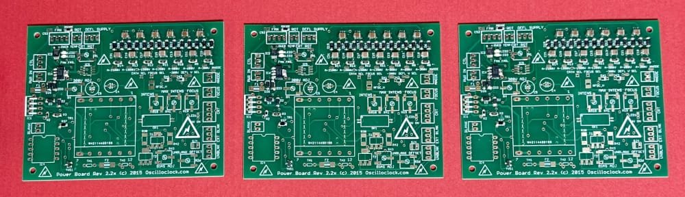
    Yes! But to be more precise, it’s the Oscilloclock printed circuit boards that come three at a time. Here you can see three boards being assembled:

    The Oscilloclock lab — where life happens in triplicate!
    These three Power Boards still have a longgggg way to go…

    Why in Threes?

    Well, every component of your Oscilloclock is manually picked from a bin, manually placed on the board, and manually hand-soldered.

    In a standard Oscilloclock model such as the Model 1 or the Exo, there are more than 300 individual parts!

    Picking, placing, and soldering just one board is onerous. Two boards? Tedious! And in such finite physical space, four boards is futile. Three wins!

    Wait – do you even procure in Threes?

    Each bin contains multiples of 3 + a bit extra

    Yes. We order parts from reliable distributors in very small quantities. The magic formula is a small multiple of 3, plus an extra one or two to fit minimum quantity restrictions and to cover parts attrition. The duly received parts are then manually unpacked and manually placed into the bins.

    By the way, parts attrition is the phenomenon where parts are wasted: misplaced, incorrectly mounted, or broken during assembly. At the Oscilloclock lab, we are proud to have an average attrition rate of less than 2%!

    Why procure parts in such tiny quantities?

    Ordering in large quantities is cheaper.

    But — we want the latest and greatest for our Oscilloclock owners! Even for the exact same component type and the same manufacturer, fresh lots may perform better and/or last longer than older lots, thanks to advances in design or manufacturing processes.

    Additionally, Oscilloclock circuit designs are constantly evolving. We prefer to adapt to newer component types regularly (with a few exceptions).

    Having a huge backlog of old stock would encourage us to stagnate. No way!

    Why not “mass produce”?

      Simple. Our motto is ‘Hand Crafted Scope Clocks’! This means an artisan design and assembly process, right down to the soldering.

      This fits with the Made In Japan mantra and the country’s ものづくり (monozukuri) culture. In an era where board factories are exclusively located overseas, embracing hand assembly helps keeps things local.

      Lastly, factory procurement and assembly is more costly in Threes. And we don’t want to increase quantities, as we constantly evolve the designs.

      But isn’t hand assembly a lot of effort?

      Yes, it is. Procuring the parts and assembling the boards takes hours. But it’s worth it to our Oscilloclock engineers!

      • The sheer joy of hand-crafting something for someone else.
      • The control over aesthetics such as precise component placement.
      • A dopamine rush as anticipation grows to the climax of final testing!

      We DO use factory assembly sometimes…

      That said, we aren’t silly! We DO use factory assembly for bespoke work where miniaturization or performance demands outweigh the joys and aesthetics of hand assembly.

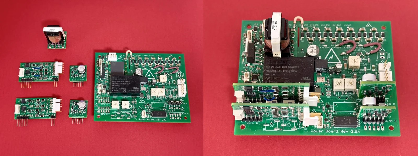
      For example, the heavily specialized Oscilloclock Core Duo System below is designed to drive dual-gun cathode-ray tubes in a very small form factor. At this level of miniaturization, factory assembly is a given.

      The Oscilloclock Core Duo System! 90% factory-assembled

      What else is “Hand-Crafted”?

      Acrylic. We use cast acrylic (not extruded). The raw material is manufactured in Japan, and then machined locally, by hand, and to order.

      You guessed it – we order custom acrylic parts In Threes!

      Fan mounts. We’ve shown this before, but we can’t help but show it again!

      Cables and Harnesses. Hand- everything! See our earlier write-up.

      The Printed circuit boards themselves? No! Sorry to disappoint you, poor reader, but the last time we etched PCBs was for the Prototype. With all the messy chemicals and finicky alignment required for double-sided boards, we draw the line here!


      They say, “Good luck comes in threes”. We think so. And our patrons must think so, for several of them have commissioned three (or more) devices!

      Do you want to explore possibilities? Reach out with an idea. Or three!

    1. Harness Handiwork

      Remember the promise we made at the end of the Heavenly Harnesses post?

      Next time we craft up a CRT harness, we’ll snap a few photos along the way. It’s a surprisingly deep topic!

      The opportunity came in April, when [Nick] commissioned an Oscilloclock Exo as a birthday gift for his father. What a thoughtful son; what a lucky dad!

      So – time to get the camera out and take those promised shots!

      The Harvest

      Spring. Such a lovely time of year! Birds sing, bees buzz, and the bottomless bellies of big auction houses swell as people go about their spring cleaning, throwing out their clutter of yesteryear.

      Spring is harvest time. Vintage valve test equipment bounty for salvaging, scavenging, and scraping. And we hate to see a scrapping…

      … which is how a key part for [Nick’s] dad’s Exo’s CRT harness was obtained!

      That’s right. Every Oscilloclock Exo harness incorporates an original brown bakelite CRT socket, specially harvested from rescued equipment.

      After a CRT socket is harvested, all existing wires are desoldered, and the socket is cleaned thoroughly to remove all traces of residue. We even polish the bakelite, to bring out a beautiful grainy texture and lustre!

      What Wire?

      Voltage, voltage, and more voltage. The more the better, for a bright and sharp image – to the limit of the CRT’s specifications, of course!

      [Nick’s] dad’s Exo’s CRT would be driven by a potential difference of 2,000 volts. Given time, the insulation in standard hookup wire would be punctured through at this voltage, resulting in arcing or even worse: fire or electric shock.

      We don’t take chances! Oscilloclock CRT harnesses are made from silicone wire, rated at 3,000 volts and 150°C. Remember we talked about longevity? We weren’t joking – this wire weathers whatever, forever!

      Stripped & Secured

      Measuring and cutting is great fun! We all learned this in pre-school. But the essential skill of stripping wire comes much later in one’s life.

      It’s a delicate operation. Strip too much, and stray strands could short-circuit. Strip too little, and the solder joint may not be secure.

      In the Oscilloclock lab, almost everything is done by hand. But we pride ourselves on using the correct equipment, where it matters!

      After stripping comes soldering. This skill can literally be studied and improved upon for years, given the varieties of solder, flux, irons, and application techniques out there. At Oscilloclock, your lead engineer (and author…) has been soldering since the age of six, taught by Grandpa…

      Lab-quality equipment also plays a key role in reducing dreaded ‘dry joints’.

      After soldering, we slip on heatshrink tubing – this protects the naked terminals from dust. It also minimizes the potential for arcing across the air gap, especially in a high-humidity environment.

      The 3 E’s: experience, expertise, and expense. All to keep [Nick’s] dad safe from the dangers of a loose wire floating around at 2,000 volts!

      Shall we Shield?

      Yes! In [Nick’s] dad’s Exo design, there are a few wires that carry AC signals. Even worse, they carry high-frequency pulses.

      Remember the days of analog television and radio, when you brought a modern electronic device such as a computer or a phone close to the antenna? You saw (or heard) electromagnetic interference (EMI). Snow, buzz, hiss – this was all because the offending device was transmitting a signal!

      We won’t go into theory here, but yes – we do want to shield these wires.

      Finally we’re ready to apply the external sheath. This is made from a braided material to provide strength yet flexibility. And it looks great!

      We also slip on a specially designed rear cap (backplate), which has been custom-machined from black acrylic. This keeps dust, prying fingers, noses, or snouts out of the terminals. Nylon spacers safely insulate the screws (stainless steel, of course!) from the terminals.

      French Connection

      What image does “France” evoke for you: Romance? Fashion? Food?

      For us, it’s connectors! With its leading presence in the aerospace, space, and military industries, French engineers have created connection technologies that rival all others in handling severe environments.

      And we need a good connector for the other end of [Nick’s] dad’s harness. One that handles high voltages. One that’s fashionable. Romantic. Delicious, even! And France1 delivers it all:

      1. The company in question has since been acquired by a U.S. corporation. But we still classify the system as “French” due to its origins. And because it sounds good! ↩︎

      Critical Crimping

      Oscilloclock owners choose their preferred level of decadance. This even applies to the pins used in the connection system!

      But whether they select the extravagantly gold-plated, or just the basic tin, we need to affix the wires to the pins in the most reliable possibly way. We need to crimp!

      Crimping is the process of squeezing the metal tabs at the rear end of the pin around the strands of the wire, making an incredibly strong and low-resistance connection. The science behind this is amazing, and is worth its own article! For now, take our word for it – never solder when you can crimp.

      And as usual, we don’t scrimp on the crimp. [Nick’s] dad deserves the best:

      Finishing touches

      At last! The harness is looking like a harness.

      At the final stage, we insert the pins into the plug, apply a specially grippy heatshrink onto the Oscilloclock end of the cable, and insert a small strip of silicone rubber prior to tightening the cable stay.

      And voila!


      Like what you see?

      We love to harvest, harness, and handcraft. If you have exotic cabling requirements for your dream Oscilloclock, or indeed any custom cathode-ray tube connection system, it would be a delight to discuss! Contact us.

    2. The Secrets to Long Life

      It’s a sobering thought, and not a particularly pleasant one, that your Oscilloclock might just outlive you

      But let’s not dwell on such talk! The real focus today is the oft-asked question: “How long will my Oscilloclock last?”

      The honest answer is: we don’t know.

      However, we do know how we try to maximize longevity, and we do have repair and return statistics from 15 years of delivering beautiful Oscilloclocks. We’ll go through all of this with you!

      Your Oscilloclock

      There are many different models and styles of Oscilloclocks (see the Gallery), with infinite variations in terms of parts that make up the final product.

      But in terms of longevity, we can broadly categorize components like this:

      • CRT – the cathode-ray tube display
      • Hardware – the case, mounting supports, thermal parts, nuts and bolts
      • Oscilloclock boards – the electronics designed and built right here in the Oscilloclock lab
      • Original device circuitry – the host device’s original electronics that are kept in use (if any)
      • Harnesses and cabling – wires, plugs and sockets; both internal and external

      In today’s post, we’ll tackle the proverbial elephant in the room – the CRT!

      Your CRT

      Your clock’s cathode-ray tube is actually a type of vacuum tube. There is a glass enclosure, with a screen coated with chemical phosphor. It has a heater (or filament), and other electrodes made of special materials. These are welded to wires that are soldered to pins protruding through airtight seals in the glass.

      Each italicized word adds up to this: A CRT is quite fragile!

      The CRT – easily the most delicate part of any Oscilloclock!

      CRTs have many “failure modes” – and we’ve seen them all! Let’s explore.

      Failure mode A: Natural causes

      Vacuum tubes (or valves) rely on thermionic emission. Electrons are emitted from one of the electrodes called the cathode, when it is heated up and voltage is applied.

      In a CRT, thermionic emission is used to create the all-important electron beam

      In any vacuum tube, this emission capability decreases over long periods of active use. This is most commonly due to a degradation of the special emissive material and coatings that are used in the cathode.

      Your Oscilloclock’s beautiful CRT will face the same issue eventually. As the number of electrons bombarding the phosphor screen decreases, the image will gradually get dimmer and dimmer, until eventually it cannot be seen.

      How long will a new, unused CRT last before it succumbs? Well, manufacturers quote working lifespans of tens of thousands of hours of active use (heated and voltage applied). This equates to a few years.

      We want our Oscilloclock CRTs to last decades, not years! So what do we do?

      Secret 1: Auto Power Off

      Strongly recommended by Oscilloclock labs, this feature simply turns the Oscilloclock off after a period of non-activity (not touching the control). Alternatively, owners can set a specific “Off at:” time.

      It may sound counter-intuitive, but in practice, all Oscilloclock owners to date have been comfortable to turn their unit on just when they intend to enjoy it, and allow it to switch itself off.

      For clocks that are permanent fixtures in offices and restaurants, staff manually turn their clocks on together with other appliances in the premises, and set them to turn off at the business closing time.

      Secret 2: CRT type and manufacturer selection

      While working with the owner to choose their CRT, we emphatically avoid tubes where the manufacturer quotes short lifetime ratings.

      Sadly, some CRTs that are most readily available today fall into this category. See the data sheet below, specifying an incredibly short maximum longevity of just thousands of hours!

      Q. What can be done for a CRT ‘on its last legs’?

      Sadly, it isn’t feasible to restore a dead CRT to factory condition. But there are two things that can be done before it reaches that state, to prolong the inevitable:

      Firstly, Oscilloclock owners can adjust the Intensity control, as described in the Operation Guide. This will drive the CRT harder and brighten the image.

      Secondly, here in the Oscilloclock lab, we can attempt a CRT rejuvenation. This procedure involves carefully applying higher-than-normal voltages to the heater, and between certain electrodes. Done correctly, this can ‘peel back’ a thin layer of the cathode surface that has degraded or suffered from ‘cathode poisoning’, to reveal a more emissive layer of material beneath.

      Q. Will a new (unused) CRT last longer than a used one?

      Theoretically, yes.

      BUT in all our experience at Oscilloclock.com, we see no evidence that new-old-stock CRTs last any longer than used ones.

      Why is that? Well, most CRTs we use are harvested from laboratory test equipment. Most operators typically switch lab equipment on only when needed – so the accumulated operating time is often very short.

      In fact, we openly encourage the owners to choose a pre-loved tube! We vet all our CRTs, testing them electrically and inspecting for any damage to heater, phosphor, glassware, or seals. No electrode is unturned; no emission-impacting detail is omitted!

      Failure mode B: Humpty Dumpty

      Humpty Dumpty sat on a wall…
      Humpty Dumpty had a great fall…

      Visit A Humpty Dumpty CRT for a truly woeful tale…

      If the CRT glass is cracked or broken, there will be rapid loss of vacuum inside, halting all electron emission. If voltage is applied, the heater will quickly burn out, due to oxidation.

      All the king’s horses and all the king’s men,
      Couldn’t put Humpty together again.

      Sadly, several CRTs have arrived at our lab in this woeful state.

      Secret 3: Shipping precautions

      We take great pains to ensure that Oscilloclock owners do not experience a Humpty Dumpty episode.

      • CRT mounting – in all Oscilloclock models we ensure the CRT is mounted with sufficient cushioning (silicon or rubber) against its mechanical supports.
      • Double-boxing – all separable components of an Oscilloclock are individually boxed prior to packing into a larger box for shipping.
      • Packing material – we use a combination of bubble wrap, foam peas, and Styrofoam to cushion the internal boxes and their contents.
      • Box selection – we love to recycle, and we have loads of used boxes on hand. We pick the stronger ones and make sure they are the right size – large enough to fit cushioning material, but never so large that the inner boxes might slide around!
      • Carrier – we have had extremely good results with the standard EMS service available from Japan Post, and this is what we always recommend.
      • Insurance – we always insure the shipment to a sufficient value.

      Thanks to this secret, to date we have only had one case of breakage for an item shipped out from our lab! And even then, the insurance claims process working with Japan Post was quite straightforward – if not even pleasant.

      Failure mode C: Gassy CRT

      No, CRTs can’t eat too many potatoes! But CRTs definitely do not like air.

      A CRT may become “gassy” if too much air leaks in via the pin seals or a fracture in the glass, such that its internal self-healing mechanism (formed by the getter electrode) is overwhelmed.

      On a gassy CRT, the image will become dimmer and dimmer until it disappears entirely.

      While there is no true remedy for this malaise, an owner can postpone the inevitable by adjusting the Intensity control. And in rare cases, the CRT rejuvenation procedure described earlier may stimulate the getter electrode to mop up some of the excess gas.

      Secret 4: Avoid potatoes mechanical shock

      Gassy CRTs crop up occasionally, usually as a result of excessive mechanical stress or shock.

      Besides shipping precautions (Secret 4), we are even careful when storing CRTs. Being situated in the Japanese archipelago, the Oscilloclock lab and all its contents must endure significant earthquakes occasionally.

      We therefore place the most precious CRTs in strongholds – small cavities in the woodwork that suffer less shaking and are very unlikely to collapse (even if the rest of the lab does). Touch wood!

      Failure mode D: Phosphor burn

      Roughly 10% of the CRTs we harvest exhibit a permanent scar, prominently visible to the naked eye…

      Phosphor burn – it looks ‘on’ even when it’s off!

      To understand why this occurs, first think of an iron burn. If you deliver too much heat for too long into the same spot, your nice new Oscilloclock brand T-shirt will feature a prominent (and permanent) mark as shown below.

      Iron burn – this shirt’s fibres have been literally scorched!

      In a CRT, a beam of fast-moving electrons bombards the phosphor coating on the screen to produce an image. If the beam is too intense, or it is allowed to trace the same route on the screen over a long period of time, the phosphor compound may degrade and lose its luminance. The result:

      • The screen won’t light up well in those spots any longer.
      • The damaged areas may appear dark even with the power off – a ‘ghost image’.

      Devastatingly, it just isn’t possible to restore the phosphor. But since these CRTs are otherwise perfectly healthy, we put them to good use in the lab for testing and experiments.

      Secret 5: Choose a decent CRT

      Some CRT types and brands are more susceptible to screen burn-in than others. Some factors include:

      • The factory list price (you do get what you pay for)
      • The manufacturer’s credit rating for reliability
      • The phosphor compound used
      • The thickness of the phosphor coating
      • Any additional technology; e.g. aluminized screens

      For more details, see our deep-dive post: Burn-in? Nope!

      Secret 6: Screen-savers and other protection mechanisms

      Remember the phrase “screen saver”? In the pre-LCD monitor days, most computers employed some form of software that would stop the same image being displayed for too long, to avoid screen burn-in.

      In addition to Secret 1 (Auto power off), Oscilloclocks have several more screen-saving features that protect the phosphor:

      • Hourly XY Bump – shifts the image by a small amount in the X and Y directions every hour
      • Auto screen switch – cycles through the screens (clock faces) at regular intervals
      • Bright/dim control – switches between preset beam intensities via a front-panel control (on some models)
      • Intensity control – manually adjust beam intensity if required to suit darker rooms

      For more details, see our deep-dive post: Burn-in? Nope!

      Failure mode E: Disconnected electrode

      Very rarely, the weld between an electrode and its connecting wire fails. Or the soldered joint between the wire and the external pin fails.

      The symptoms depend on which electrode has been disconnected, but one thing is for sure: the CRT becomes defunct. How awfully sad.

      Secret 7: Cry and move on…

      I would like to simply write, “Choose a reliable manufacturer.” However, they don’t get much more reliable than Tektronix!

      Besides protecting the CRT from mechanical shock (see previous Secrets), all we can do is accept fate…

      Failure mode F: Open heater

      A CRT heater (filament), just visible

      Remember incandescent light bulbs of yore, with a delicate filament wire suspended inside the glass? They burned out over time – typically with a break in the wire that you could even see with the naked eye!

      Well, the heater in a CRT is also formed from filament wire (albeit with different metals designed to emit more heat than light). If a CRT heater burns out, the cathode cannot be heated sufficiently to emit electrons, and the tube is rendered useless. A sad, sad state of affairs…

      But what causes such failure?

      Well, when did light bulbs typically fail? Yes! Right when you switched them on!

      The reason is that a cold filament has a very low resistance. When you apply voltage, a huge amount of current flows (called inrush current). This settles as the heater warms, but the initial power and sudden temperature change causes metal fatigue. And after many switch-on cycles, the wire can break.

      Secret 8: Soft-start!

      The best way to preserve the heater is to limit the inrush current, so that the filament can warm up gradually. Every Oscilloclock employs one of the following 3 types of inrush current limiter:

      1. The sacrificial lamb – a light bulb!

      In this scheme, we simply place a specially-selected incandescent light bulb in series with the CRT heater. Upon switch-on, most of the supply voltage is applied to the light bulb’s filament (because the CRT heater’s resistance is low), making it light up brightly.

      Primitive. Low-cost. Yet immensely effective!

      As the CRT heater gradually warms up, its resistance increases. The voltage across the light bulb decreases, making it dim and cool down, and its resistance lowers. By this time, the CRT has fully warmed up and stabilized, with most of the voltage now shifted to the CRT heater.

      Functional, AND beautiful to watch! Besides the Exo in the video, we’ve used it in the Heathkit OR-1 Oscilloclock and a few other custom pieces.

      2. Mister thermistor

      These long-legged beauties are called thermistors. They have an odd characteristic called NTC (negative-temperature-coefficient). The hotter they get, the less their resistance!

      Does that sound familiar? Yes! They can replace the light bulb used in method (1) above. Most of our Oscilloclocks employ these devices, because they are reliable, predictable, and very small.

      Nonetheless, we enjoy the switch-on supernova of the old-fashioned light bulb. And some owners do, too!

      3. Electronic soft start

      Both light bulbs and thermistors are passive devices; their resistance vs. temperature profile is known (and can be charted in a specifications sheet). BUT they are not aware. They don’t have any kind of feedback loop, so they don’t actively control the voltage across the CRT.

      Recent Oscilloclock Power Board designs provide an active soft-start option. This is a circuit that dynamically ramps the output voltage up from 0V to the final voltage in a preconfigured number of seconds.

      Effective and reliable, but just a little more complex!

      Q. Will running the heater at a lower voltage prolong the CRT?

      No. According to many folks, running filaments at lower voltages than specified can accelerate “cathode poisoning” – degradation of the cathode material due to absorption or chemical reaction with trace foreign substances. We don’t recommend this.

      Q. “Sacrificial lamb” approach – won’t the light bulb itself die?

      Yes, eventually. However, it will certainly outlast the CRT filament. Although the light bulb filament does suffer a high inrush current, even a cold CRT presents a small resistance into the circuit. The voltage across the bulb at turn-on is therefore less than its rated voltage, and this extends its life.

      Q. Isn’t there something that can be done to restore a CRT heater?

      Maybe. Some folks have managed to ‘fuse’ a broken heater together, by injecting a very high voltage (thousands of volts) across the gap. The resulting arc effectively welds the broken filament. We haven’t yet had the pleasure of trying this, but if we do we will certainly write it up for you!


      Replacing the CRT

      Fact: In 15 years of crafting Oscilloclocks, not a single unit has ever come back for CRT replacement!

      That said, every CRT we shipped will reach its end of life. It’s just a matter of time.

      But don’t despair! Oscilloclock carries spares for most common tubes, and we can supply and replace them. Some owners even choose to purchase spare CRTs with their original order, so that they have them on hand.

      Q. What about rare CRTs?

      If a clock was crafted from a particularly rare CRT, there may be no spare available. But again – do not despair! We can work with the owner to select another type of CRT, and modify their precious device to suit. By rejuvenating their clock ‘with a twist’, the owner may experience even more of a thrill than if we simply restored it to its previous state!

      A rare CRT: type D4P. Don’t worry – we can replace it with something!

      Q. Can owners replace the CRT by themselves?

      We always recommend shipping clocks back to the lab for CRT replacement.

      However some models, especially those in the Oscilloclock Exo series, employ a simple and safe mechanism to swap CRTs – and we provide instructions in the Operation Guide for doing this.

      Q. Does Oscilloclock.com produce or repair CRTs?

      No. We dream of one day establishing a CRT factory. Or at least a CRT repair facility. However with all the toxic chemicals, high vacuum, glasswork, and intricate welding involved, this is likely to remain a dream.

      Q. Are new CRTs being manufactured anywhere in the world?

      Yes – some types of CRTs are being manufactured in some countries. However many are not suitable for Oscilloclocks. They may employ electromagnetic deflection (which we don’t yet support), they are special-purpose for military or aerospace applications (too expensive!), they are very cheaply-produced (not reliable), or they have short lifetimes per design and require frequent replacement.


      Swappable CRTs!

      Many of our ‘Full Package’ type clocks (see Gallery) support display swapping.

      Essentially, we craft complete additional display units, which the owner can swap in at will simply by swapping cables to the Control Unit. There is no need to open a case, touch the CRT itself, or any form of delicate operation.

      This is normally used to change the ‘mood’ of an Oscilloclock, by swapping in different phosphor colors. But it also can be used to more easily swap in a replacement CRT.


      Do you want long life, both for yourself and for your precious electronic devices? Are you tired of modern society’s throwaway culture, built-in obsolescence, and device non-serviceability? Our goal: electronic artwork that might be passed down a generation (or more) in actual working order!

      Stay tuned for Secrets Parte II, where we will explore the life of other components!