Let me introduce [Howard]. He loves electronics, has a bunch of old scopes, is obsessed with time accuracy, and happens to be a retired medical doctor.
What do you give a chap like Howard for his birthday?
Well, his loving son [Nick] had the answer! He gave his dad the ultimate gift – an Oscilloclock Exo 3KP1 with a custom medical-themed animation!
Hong Kong connection
[Nick] first reached out in February to check out his options. He explained that the family was spread across continents, but would be uniting in Hong Kong for the big birthday event, in June. Four months away!
Could Oscilloclock deliver something glorious and mesmerising for his dad – but in time, and within budget constraints?
Yes and yes!
The lab just happened to have a set of fully assembled, older-revision boards just begging for love and attention. And also in stock was a beautiful new cast acrylic Exo case and CRT ring set — with some slight imperfections.
By using these components, we could reduce the time needed to craft the device — and offer a substantial discount to boot!
The clock was ready and shipped a week ahead of time – making sure [Howard] would not go disappointed on his big day.
Perfectly Imperfect
Frequent readers may recognise that your humble Oscilloclock senior engineer has perfectionist tendencies. Any “slight imperfections” come with some concessions.
On the other hand, owners rarely perceive such imperfections as such. They either don’t notice them, or they actively enjoy them as features, making their beloved device just that much more unique.
Quiz time! Can YOU spot any blemishes?
Make a wish!
[Howard] no doubt got quite a surprise when he turned on his birthday present and saw it literally light up the room!
No, this was not a pyrotechnic effect made specifically for the occasion! It’s called an inrush current limiter, designed to preserve the longevity of the CRT.
Howard’s device employs what we call “a sacrificial lamb”. In this scheme, a light bulb is used to absorb most of the switch-on current that would otherwise flow directly into the CRT heater. The bulb lights up brilliantly for a time, then dies out as heater resistance increases and current decreases.
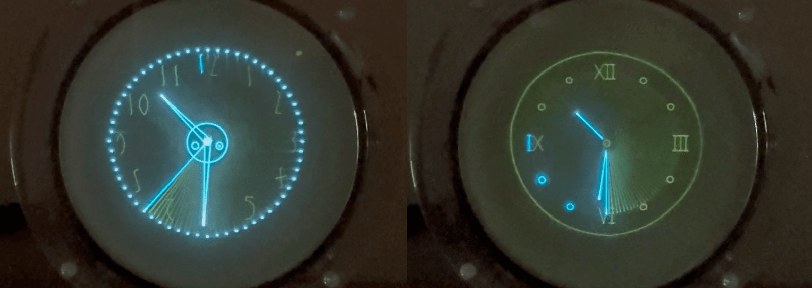
The Oscilloclock Exo is a popular model. But every clock simply must be unique! [Nick] had just the trick in mind, with a request to incorporate the words “What’s Up, Doc?” to reflect his father’s illustrious medical career.
Can do. But we took it a small step further — a simple animation depicting a patient standing behind an X-ray exposure screen!
Eye candy. Proudly minimalist animation on proudly minimalist hardware!
Post-ceremony
Private birthday celebrations are private; we have no photos to share here of the ecstasy we hope [Howard] felt when, surrounded by [Nick] and his loving family, he unwrapped his birthday gift.
However we do have a photo of the clock in-situ, after the trip back home:
We wish [Howard] many future returns and thank [Nick] for the opportunity to bring joy to the family on their special occasion!
Like what you see? Do YOU have a special person who deserves a special work of art? Let us know. We even gift-wrap!
Like what you read? Every article here has been crafted by hand! While we use AI for idea generation and research, we never use it to write content or even to adjust the tone. What you read comes directly from the heart. Enjoy!
We love to re-use, upcycle, recycle, restore, re-invigorate!
We scour the planet, rescuing unique-looking cathode-ray tube based devices from certain destruction. We have oodles of oscilloscopes, spectrum analyzers, capacitor testers, audio monitors, medical instruments, television broadcast equipment, engine analyzers, and so much more!
Check out these newly arrived devices, just waiting to become Oscilloclocks:
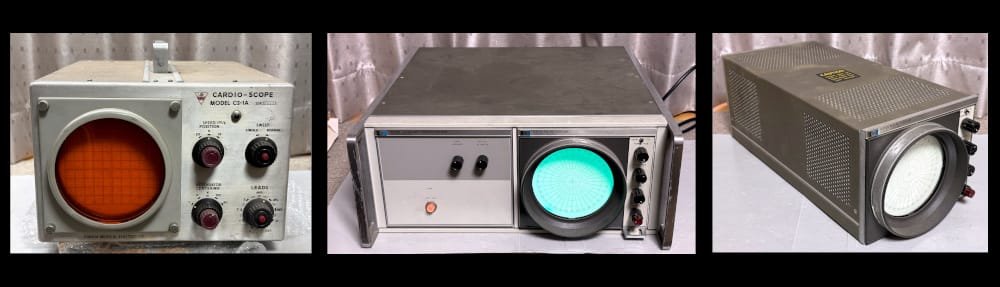
Fukuda CS-1A Cardio-Scope
A bed-side heart rate monitor, used in hospitals of yester-yore.
By default fitted with a long-persistence 5″ CRT and amber filter.
A colourful addition to any bedroom!
HP 8414A Polar Display
This early 1970’s Hewlett Packard green-screened device will take your living room straight back to the Space Age! The display is rack-mounted by default, serving up a full NASA look-and-feel.
And removed from the rack, the 8414A is as cute as a button! It’s the perfect size for your desk, coffee table, or display case.
And for the truly serious NASA enthusiast, we might rack-mount the display next to a blue-phosphor HP 8412A Phase-Magnitude display. A dual-display visual virtuoso!
Cleaning, restoration, and modifications
These devices are original and deliciously dirty! We’ll do our best to clean, polish, wax, and otherwise restore every surface as much as practical.
If you really want, we’ll re-paint, re-plate, re-finish, or re-anything – to get you the right look & feel.
We can modify with cast acrylic side panels, custom-turned wooden knobs, or brass bezels. We can do anything, in theory. Warning: diamond-studded escutcheons do tend to be rather expensive.
Our default recommendation is to bypass all the existing circuitry with a full set of Oscilloclock boards that drive the CRT directly. This ‘full conversion’ approach gives best performance, maximum reliability, and allows us to offer a full 3-year warranty on all components (except the CRT).
But some devices are, miraculously, in partial or even full working condition when discovered! If the device can be electrically restored, we can apply a ‘minimal invasion, maximum re-use’ policy – keeping the existing circuitry alive, and installing only what’s needed to control the display. While reliability and performance suffer, this allows us to keep the original controls mostly functional, for the ultimate in twiddling pleasure!
Stripping and weight reduction
Many vintage devices are heavy! For owners who are less fastidious about maintaining internal originality, we can strip out unnecessary components and circuitry to lighten up the final product significantly.
Some owners take this option, but additionally request that we retain every wire, board, and screw in a separate box for them to admire. We applaud their fascination in their device’s history and its engineering culture!
If you like the look of these new-found beauties, let us know. If you don’t, let us know. If you have your own beloved device to convert, let us know.
Nestled amongst the standard features that come with all Oscilloclocks is a special effect called “Slow motion”. We suspect very few owners have noticed this feature, and fewer yet have actually tried it! It hasn’t been very well advertised… Until now!
This Exo really likes the slow life!
No, this video is NOT just being played back slowly.
It’s the graphics rendering itself that
has
been
slowed
down…
Welcome to the Slow motion feature!
What is it doing?
As described in Circle Graphics, every image and character shown on your Oscilloclock is constructed from segments. Each segment is actually an ellipse, arc or a line.
Normally, an image (or text) is displayed on the screen by drawing its segments very quickly, all within the time of one frame. Each frame is completely redrawn 50 times per second. By repeating the drawing so rapidly, and adding in some persistence effects of the CRT phosphor, the human eye can’t see individual segments being drawn.
But when “slow motion” is enabled, only one segment is displayed per frame. For an image or text with 50 segments (at 50 frames per second), it would take 1 second to draw the entire image. At this rate, the eye can easily distinguish each segment as it is rendered!
Even the original Prototype from 2009 boasts this glorious feature!
Enabling slow motion
It’s in the menu!
Menu → Effects → Slow mo delay
A delay value other than 0 turns on the effect. This number indicates the number of frames that each segment will be displayed, before moving on to the next segment. Increasing the number therefore makes for a “slower” rendering of the image.
In the above videos, the delay was set to 1. Here’s what it looks like when set to 10!
Hybrid fast & slow motion!
In the videos so far, you’ve seen the slow motion effect applied only when rendering characters – numbers and text.
This is by design! Most graphics, figures, and images are intentionally left unaffected, so we can enjoy hybrid screens, like the below two examples!
Hybrid slow motion – graphics are fast; numbers and text are slow!
Phosphors and persistence
At this point in the article, dear Oscilloclock owner, you must have tried out the feature on your own device – and you probably noticed a key difference in behaviour…
No doubt you could observe the individual segments being drawn, but they disappeared so rapidly that you couldn’t catch the entire image!
What’s going on? Were all those cool videos above doctored in some way?
Absolutely not!
This P1 phosphor isn’t very persistent…
The difference is the phosphor in your CRT. Most Oscilloclocks to date have shipped with a green P1 or P2, blue P11, or amber P12 phosphor CRT. These are all beautiful phosphors, but they are relatively “fast”. They emit light quickly and brightly when struck by the electron beam, but they have very little persistence; the light fades relatively quickly.
Enter the P7 phosphor! This incredible chemical first fluorescences (lights up) in a pale violet/blue colour, and then phosphoresces (persists) for some time in a yellow colour!
Are you into slow food? Enjoy the slow life? Want to slow down even more? This feature is for you. Sit back, relax and watch electrons traveling at the speed of light actually form characters on your Oscilloclock!
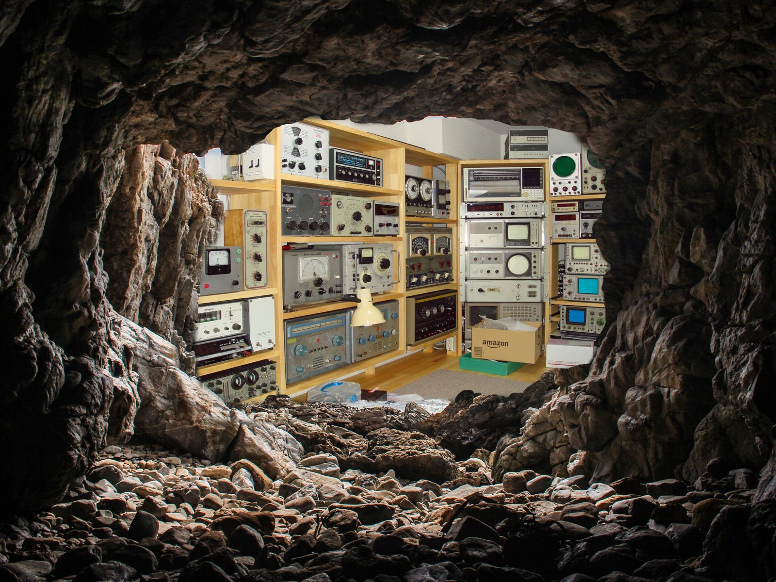
Here at the Oscilloclock lab there’s nothing more pleasurable than helping put a cherished vintage oscilloscope back into action. A new lease on life!
That’s why when [Chris] reached out about his early 1970’s Conar 255 oscilloscope, wanting to convert it into a Vectrex gaming machine, we were naturally excited!
The original Vectrex was an incredibly cool device. Instead of the pixelated, blocky graphics of the time (anyone remember Pac-Man?), the system used vector graphics to draw smooth line-art images. Each vector was a straight line, or a smooth arc, connecting point A to B. Vectrex games were true works of art, and the original hardware is quite rare (and $$$)!
Well, [Chris] caught the vector graphics bug. But he decided to build a Scopetrex – a hardware emulator that allows you to run Vectrex games on an oscilloscope! He would theoretically just connect this to the Conar 255’s existing X, Y, and Z (blanking) inputs.
We like this “minimum invasion, maximum re-use” approach. We’ve gone down this route numerous times to craft Oscilloclocks out of still-usable hardware. (The alternative? Install a full set of modern boards that drive the CRT directly.)
Sample specimens of “minimum invasion, maximum re-use”
[Chris] got down to planning. He could interface the X and Y inputs easily. But he faced a problem with the Z (blanking, or intensity modulation) signal, which instructs the scope when to turn the beam on and off:
The Scopetrex outputs a 5V DCdigitalblanking pulse.
The Conar requires at least 20V peak-to-peak blanking signal – and employs analog AC coupling.
We’ve solved this mismatch problem before using various non-standard Oscilloclock board setups and complex hook-ins to the existing circuits. Always on a case-by-case basis, always unique.
But now, at last, it was time to standardise the process. To make it easy. To adapt any vintage oscilloscope for digital blanking from a microcontroller! We proudly announce the next member of the Core family: The Z Core!
The Z Core (in this case, a Z Core 2 Ex) …
… joins the Oscilloclock Core family!
How to install it
Believe it or not, the minimal installation requires just 3 steps. For almost any oscilloscope! The Z Core effectively sits in series between your device’s blanking supply and the CRT grid.
Snip the wire connecting to CRT grid.
Connect the orange wire from the Z Core to the circuit side of the cut wire.
Connect the green/yellow wire to the CRT grid.
Snip.Connect!
Visit the Z Core Support Page for lots more detail, including the obligatory warnings about high voltage. There are also details on how to connect the Z Core to your controller, detailed specifications, and some fun Q&A to help answer your most burning questions!
The Z Core 2 Ex!
We’ve wanted to develop a dedicated, built-for-purpose Z Core product for a very long time. This would consist of a single, miniaturised, low-power board called (ingeniously) a “Z Core Board”, and a few harnesses.
But [Chris] didn’t want to wait for Oscilloclock labs to work through its ever-growing bucket list. Could we deliver within 2024?
Yes!
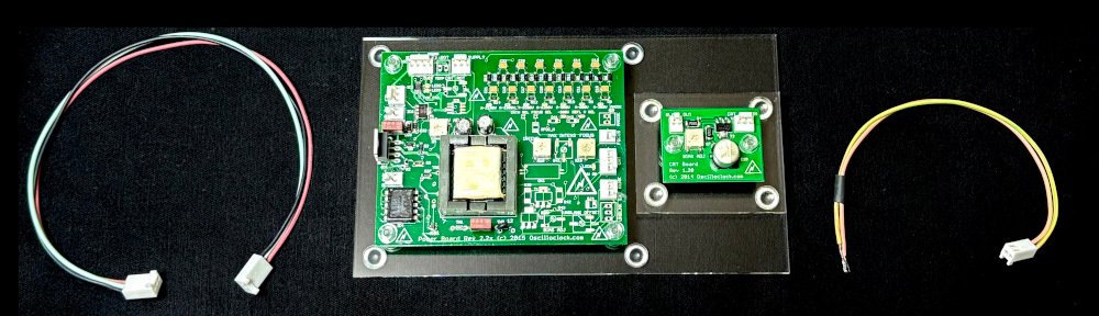
In past retrofits such as the Kikusui 537, we’ve taken spare boards that were originally designed for fully-featured Oscilloclocks, and partially populated them with only the necessary components to serve the blanking purpose.
Partially populated Oscilloclock Power Board
For [Chris], we found an almost fully-populated new-old-stock Power Board v2.27 and compatible CRT Board v1.21 lying around, just dying to be used and loved by someone. Older revision boards do tend to be set aside, as folks want the latest and greatest.
With just a few minor modifications, this assembly shipped – and is now branded as the Z Core 2 Ex. The “2” refers to the Power Board’s major revision, and the “Ex” stands for “external blanking amplifier” (the function of the CRT Board). The Power Board rev2.2x series boasts an on-board blanking amplifier, but this section wasn’t already populated. What a great opportunity to use up a stock CRT Board!
[Chris] will be happy. And we’ll keep up this spirit of minimising waste. You’ll see some other Z Core assemblies popping up in future: a Z Core 1 Ex, a Z Core 2, and potential variations of Z Core 3’s.
And finally, one day, a genuine dedicated Z Core will be born!
Why your scope needs a Z Core …
Many old oscilloscopes simply don’t have any input for Z blanking, Z axis, intensity modulation, or cathode modulation. (Look carefully – it goes by many names!) Or, the input may be there, but it’s not compatible with a microcontroller. Why couldn’t the designers offer a decent interface?
Well, it all has to do with high voltage! To get there, let’s cover how CRTs work in just three short sections:
Gun
A cathode-ray tube (CRT) has an electron gun that shoots electrons at the phosphor molecules on the screen. The electron beam is deflected by putting positive and negative voltages into electrodes placed in the CRT’s neck, and this is how patterns are drawn on the screen.
This is how a CRT works. It’s awesome.
But the electron beam has to be turned on and off, to break the pattern and make meaningful images on screen. This is known as blanking.
Blanking
Oscilloscopes, particularly, have to blank the beam when it goes back (retrace), from the right to the left again. If there were no blanking, you’d see a retrace line – wickedly cool for us artists, but devastatingly distracting for engineers who want to focus on the waveform itself!
Retrace lines – arty but not desirable
Oscilloclocks also rely on blanking. In Circle Graphics, where all figures are composed of lines and circles, blanking is crucial to creating meaningful segments. For example, a “C” is readily created from an ellipse “O”, simply by blanking the beam at just the right place!
A blanking pulse kills the beam to get a ‘C’
Grid
CRTs are designed for blanking. There’s a valve-like electrode called a grid that sits inside the gun, just in front of the cathode where the electrons are spat out. If you inject a negative voltage into the grid (compared to the cathode), it repels those electron babies and sends them back where they came from. They don’t bombard the screen, and no more light is emitted. Blanking in action!
Titillating! Electron field density is reduced when a negative voltage is applied to the grid!
A fuller explanation – from The Bible
The bible
A change in grid voltage influences the field distribution of the first lens, and in so doing controls the emission from the cathode. For any fixed value of voltage applied to anode 1, it influences the number of electrons which pass through the cross-over point. Let us see how this comes about. In Fig. 5-17 is shown the field distribution in the first lens for two values of grid bias, O and -30 volts, and a fixed value of voltage on the plate.? It is clearly evident that with zero bias, the area adjacent to the cathode, between the cathode and the control-grid aperture, has a comparatively high positive potential as the consequence of the field between the control grid and the first anode. Under such conditions of zero grid voltage, it has been found that the area of the cathode which is emitting corresponds approximately to a projection of the area of the grid aperture; the maximum number of electrons are passing through the grid opening and the beam-current density is high.
When the control grid is made negative by an increase in the bias, —30 volts in the illustration, the field distribution in the vicinity of the cathode is altered so that only the center of the emitting surface is behaving as an emitter. The other areas are influenced by the space charge and effectively are not emitting. The result is a reduction in beam density and several other related effects.
High voltage
So – back to the high voltage aspect. The cathode and grid are usually about 2kV (that’s right – 2,000 volts!) negative compared to the rest of the circuits. If you connected an external input signal directly to the grid, something would fry.
Old-school oscilloscope designers took a very easy (read: cheap) solution: they stuck a high voltage capacitor between the grid (or cathode) and the external signal. This is called AC coupling because the capacitor blocks the DC voltage (2kV), and only couples through the AC (the fluctuating blanking) component of the signal.
AC coupled external intensity modulation in the Conar 255 (L) and the Trio CS-1554 (R)
This method of intensity modulation was fine for the regular, repeating signals observed in old TVs and radios. But it isn’t what [Chris], or so many millions out there like him, needs! They need to send through an irregular, sometimes not-fluctuating-at-all (i.e., DC) signal. They need DC coupling! And it has to be isolated – standing off more than 2kV!
And there’s another voltage related problem: the grid has to go substantially negative with respect to the cathode, in order to completely block the electron flow. We’re talking 20-50V typically. This is not a voltage that a modern microcontroller board will deliver! This requires an amplifier.
Summing it up
So that’s it! Just three(?) words. We need an isolated DC-coupled amplifier. And it needs 2kV isolation with a 10x amplification factor.
Welcome to the Z Core!
Demo
No assembly can leave our lab without being fully tested, and without a demonstration to ensure the customer’s utmost satisfaction. Here’s how the demo went:
The host device: Trio CS-1554
This venerable Trio (also branded as Kenwood) hails from around the same era as the Conar 255. It was attractive, had fairly good specifications, and a low(-ish) price tag, making it very popular both in Japan and overseas. Documentation is freely available and… more importantly, I had one lying around!
Look carefully – it’s bulging and leaking!
Of course this device is full of high voltage oil capacitors. These were effective in their day, but they break down over time, and things get very nasty. One particular HV capacitor in this unit was overheating to the point that the metal case had warped, and oil was even leaking out! Ick.
A few modern-day capacitors hacked together replaced the leaky unit and saved the day. Onwards!
Connect Z Core outputs to Trio CRT grid and grid circuit (as shown in earlier section)
Incompatibility! The Trio’s horizontal input seemed to want 10V peak-to-peak for maximum deflection (this is way off its original specs of 250mV/cm. I think it’s broken!) The Connect by default has only a 3V peak-to-peak output signal. The image is going to be small… ↩︎
Trickery! The Connect by default is designed for a display device with a high-impedance Z input. The Z Core 2 Ex has a low-impedance input and 15mA drain at 5V. A temporary mod was needed in the Connect – which was promptly reversed after the test. ↩︎
The result? A relatively clean image, albeit small! But the blanking works well. [Chris] was okay with the jagged edges and other blemishes; these are attributable to the Trio’s rough condition.
Performance testing
The Oscilloclock cave is not a precision testing laboratory. But we do have a significant collection of equipment, and every piece plays its part. In this case, we deployed a Hewlett Packard 1901A Pulse Generator.
Choosing amongst a plethora of delightful old oscilloscopes, we stayed with the HP theme and used a venerable but still digital HP54615B.
Set output to 5V and connect to the Z Core’s input
Connect a 20pF capacitor across the Z Core’s output, via the standard 200mm 22AWG harness
Connect Ch1 of the scope to the input, Ch2 of the scope to the output
Results
Measurement
Assembly: Z Core 2 Ex
Waveform base voltage
-46V
Rise time
130 ±10 ns
Fall time
180 ±10 ns
Propagation delay
120 ±10 ns
Effective bandwidth
DC to 3 MHz (limited by rise/fall time)
These results were satisfactory. But at some point, we’ll try the same with a Z Core 1 and a Z Core 3. And one day – a purpose-built pure Z Core. Stay tuned!
In conclusion
Well, that’s a wrap! The tested assembly has now shipped, and soon [Chris] will be able to try out a Scopetrex on his minimally-modified Conar oscilloscope. Fingers crossed!
For more technical info, fun facts and Q&A, check out the Z Core Support page. And for a peek at our range of gadgets, be sure to check out the Gallery.
Today’s story began with a mail from [Eric], who’d read up on the Oscilloclock 3-inch VGA Assembly and wondered if it could be used to create an old-school serial terminaldisplay on a vintage oscilloscope CRT.
Yes it could! In fact, the Oscilloclock Lab did one better. Instead of just a VGA display controlled by an external device, we developed native terminal firmware that accepts DEC VT52 compatible commands over a serial port, and renders all text and graphics using beautiful, curvy Lissajous figures.
The stuff of dreams. The OscilloTerm Exo B7S4.
Demonstrating basic terminal features, connecting to a PC via serial cable Oh, did I mention? It’s a clock as well!
Zork, anyone?
Ultimately, [Eric] just wanted to play Zork. And together we made it happen.
The CRT. The Case.
[Eric] wanted a sleek ‘skeleton’ look. His choice of a gorgeous B7S4 CRT, mounted in custom-machined cast acrylic supports, exposes all glassware and allows for a titillating rear viewing experience.
And with a high-transparency cast acrylic case housing the electronics, the OscilloTerm Exo can be enjoyed from every angle!
Astute readers may wonder about the 2.1 kilovolts of high voltage coursing through their innocent-looking device. Rest assured! All internal wiring is sealed off, and Oscilloclock CRT harnesses are hand-crafted with heavy insulation and precautions taken against dust, prying fingers, rats, and even salivating cats.
Safety in action! Mil-spec connector (left); custom-designed acrylic cap on the CRT connector (right) An O-ring blocks dust from entering the CRT/socket gap (picture from the Oscilloblock)
This case and CRT mounting variation is branded the Oscilloclock Exo, and has proven its wow-factor at several public exhibits to date. We certainly love it, and [Eric] did too!
The Terminal.
This post would never be complete without showing you what real serial terminals from the 1970’s looked like, and explaining what they actually did! Here goes…
Terminals such as the above were physical input/output console devices, back when computers were the size of massive refrigerators, and the operator would sit remotely – at a desk in a separate area, or even a different room.
The terminal and the remote computer were connected via a cable, and would communicate each other by sending data back and forth across the cable; mainly terminal commands and ascii encoded text. Most commonly, a serial communication protocol was used to get the data safely from one end to the other – and hence the devices were known as serial terminals or even serial consoles.
Amusingly, they were also called dumb terminals, because they had no computing power of their own; they were only extensions of the computer to which they were connected.
The OscilloTerm Terminal.
[Eric] wanted a special Oscilloclock that he could also operate as a terminal, connecting it to a remote computer via cable. The remote computer would control the display, using the same serial protocol and commands as an ancient dumb terminal.
But an Oscilloclock is anything but dumb. [Eric] wanted to keep all the standard exciting screens and features of his Oscilloclock active, and only display the special Terminal screen when the remote computer started to send commands. Then, when the commands stopped, the Oscilloclock should go back to the screen it was on!
His wish was our command! Here’s a demo of smart screen switching in the final product:
Some technical Comments
Naturally, the terminal emulator firmware was written entirely in assembly language.
PIC18F2680 – the Oscilloclock workhorse.
We use assembly mainly because the minimalist PIC microcontroller used in the current Control Board revision has only 64K ROM, and an unbelievable 3328 bytes (yes, BYTES!) of RAM. To squeeze all the lovely Oscilloclock features in, while driving Circle Graphics real-time processing, the code and memory space has to be clean, tight, and heavily optimized at the machine code level.
Assembly. It’s the ONLY way to squeeze it all in!
For even more technical details, such as the list of VT52 (and VT100) commands supported by the OscilloTerm, and the various configuration parameters that can be tweaked to make the terminal emulator more ‘friendly’ when connecting to a specific device, check out the Support page. Worth a visit!
Why Zork? And HOW?
Zork is an interactive adventure game. But it’s old. And it’s text-based, because it was run on computers long before fancy graphics capabilities were widely available. The player explores mysterious locations, solves puzzles, and collects treasures while avoiding various hazards and creatures. All by reading text and typing commands and responses!
[Eric] was able to play Zork by loading the game’s Z-code into a Z-machine interpreter known as Frotz, on a PC connected to the OscilloTerm. But there was trickery involved!
He had to recompile a version of dfrotz (the dumb terminal version of frotz) to remove the status bar and audio from the game.
He needed to wrap the dfrotz output with a custom Python script to support the OscilloTerm’s 16×8 screen and simulate the required baud rate.
But now that’s done, he can play anyInfocom game that runs in dfrotz on his OscilloTerm!
What’s next?
Readers would probably agree that adding a generative AI feature would be incredibly cool. For example, the War Games feature is great, but the text on the screens is all pre-programmed. What if you could interact more naturally with your Oscilloclock?
Another one for the list!
Are you a serial serial terminal collector? Do you want to play Zork on the oddest device imaginable? Or, you fancy a clock in the Oscilloclock Exo range? Contact us and let us know!


