Building the Astro Clock

In the last post, we took a look at a funky new sidereal clock from the Oscilloclock Lab. Now let’s take a look at what fanciness went into it!

The Hardware

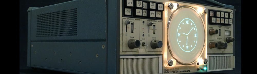
[Alan], our astronomer protagonist, wanted to install all the electronics inside his Tektronix 620 X-Y Monitor. He didn’t need a nice fancy case.

Demonstration of a Lissajous circle
No pixels here! Circle Graphics

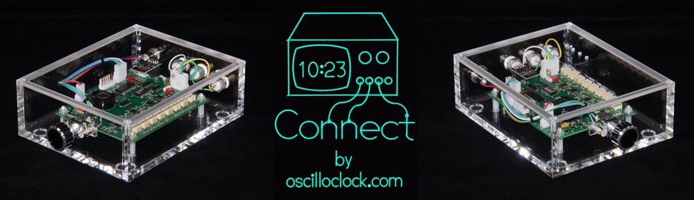
No problem! We supplied the Oscilloclock Bare – our stand-alone controller board that generates images and text rendered in smooth and silky Lissajous figures.

The board ships on a cast acrylic mount to make it easy to test externally, prior to installation into the host piece of equipment.

Next, we added the Oscilloclock Wave. This is a Wi-Fi adapter that allows an Oscilloclock to pull (Solar) time from NTP servers over the internet, keeping accurate time indefinitely.

Bare-bones Wave Core module

For [Alan], we left the cabling and aesthetics options open, and shipped the basic Wave Core module instead of the stand-alone type pictured above.

Finally, we included a decent quality power pack, to allow running the assembly prior to installation.

This would eventually be eliminated by powering the unit from the Tek 620’s internal supply itself.

The software – Sidereal time enhancements

To transform the Oscilloclock Bare into the astronomically great Astro Clock that it is today, we needed sidereal time.

Querying the sidereal API. Easy as pie!

Easy! The US Naval Observatory Astronomical Applications Department provides a publicly available API for querying sidereal time, given a location.

The Oscilloclock Wave already had features to pull earthquake data from a similar API and push it to the Oscilloclock for display. Extending this for another API wasn’t astronomically difficult.

The Wave sports a bunch of advanced settings for particularly tweak-loving oscillofans out there. We just needed to add a few more! These are to enable querying and sending sidereal time to the Oscilloclock, and to set the location.

Setting up for sidereal time

But why not just calculate sidereal time?

Some readers may have guessed that formulae and code libraries for calculating sidereal time are readily available. Why didn’t we just implement the calculation in code, and avoid depending on an external API?

Our minimalist PIC 18F2680 even had a terrible bug at one point…

Well, I’ve mentioned before that the current revision Oscilloclock Control Board uses a minimal-specification microcontroller with very limited capabilities, and is heavily optimized by coding in assembly language.

Sadly, this chip was already jam-packed to the hilt, and there simply wasn’t any more space left for the code and run-time memory needed to calculate sidereal time internally.

And writing the necessary floating-point calculations in assembly would be no mean feat!

Why Assembly Code?

Because We Can.

But, it sure ain’t easy…

So NO – we couldn’t easily calculate sidereal time, and it was API Option full steam ahead!

Astro Screens!

Even with its minimalist microcontroller chip, we’ve managed to squeeze some amazing stuff into the Oscilloclock Control Board firmware.

For more of the weird and wacky, see Screens & Things!

For this build, we needed yet more screens.

First, we used our trusty Figure Creator software to render a rudimentary telescope into Circle Graphics sprite code.

Astro Clock splash screen

We then crafted a simple Astro Clock splash screen, by adding some random circles for stars and laying out basic text around the telescope.

Finally, we added some basic digital and analog clock screens, using the same telescope figure as a centrepiece. This was mostly straightforward, but the existing clock hand drawing code did need some tweaking, to reference either solar time or sidereal time depending on the active screen.

Done!

Invoiced. Paid. Shipped. Received. Treasured forever. Right?

Wrong!

Sidereal really sidelined…

A year after [Alan] received his lovely Astro Clock, the unhappenable happened. The Astronomical Applications API was taken down!

“undergoing modernization”… a harbinger of API death! Jan 2020 snap courtesy archive.org

The site was taken offline for a planned six months, for “modernization”. [Alan]’s sidereal clock was relegated to a normal solar Oscilloclock, albeit temporarily.

But as lovers of electron beams striking phosphor, we always look at the bright side! Six months is still relatively short in astronomical terms! We resignedly marked “X” on the calendar, and bided our time.

But then… the unfathomable fathomed. The COVID-19 pandemic struck. The USNO site modernisation was completely halted – very likely deprioritised in the midst of indiscriminate illness, clinical chaos, and staff shortages.

Halted… 2 years later, still no luck… Mar 2022 snap courtesy archive.org

We waited, and waited, and waited. There were no fingernails remaining to chew when, after two and a half years, a revised API was finally made available at the end of 2022. Hooray! Thank the stars!

API resurrected

Fresh API documentation in hand, we set about modifying the Wave to use the fresh fruits of the USNO modernisation machine.

Fortunately, there were only minor changes to the API – a few more mandatory data fields, a change in date format and such. These required a relatively small amount of rework in the Wave’s firmware.

And … we were back in the amateur astronomy business.

Almost like a big Christmas present from Santa!

Was this [Alan]’s Christmas present? – Santa in your Clock

Do we regret taking the API approach?

It’s a good question. API death could happen at any time – possibly rendering the Astro Clock lifeless, listless, or lethargic yet again.

But, no. The decision not to calculate internally was valid, based on the known constraints. And we did our veritable utmost to revive poor [Alan]’s Astro Clock as soon as possible.

By the way, we at the Oscilloclock Lab certainly can’t complain about USNO’s API shutdown. We, too, have been heavily impacted by pandemic and other worldly events. As of this posting, our formal activities, too, remain on pause…

… for now!


Curious about other Oscilloclocks that use APIs? Check out the AfterShock Clock, which taps into an earthquake API to display earthquakes in (almost) real-time on a lissajous-rendered map!

Astro Clock

A few years ago, we introduced Metropolis Time, a time system based on the 20-hour, two-shift days featured in Fritz Lang’s iconic movie Metropolis.

Since then, we’ve received a few requests to craft clocks that display some other calendar and time systems – from the ancient and archaic, to the religious, to the scientific.

That’s Astronomical!

Today’s exciting story began with a request from [Alan], a prominent amateur astronomer. He happened to have a lovely Tektronix 620 X-Y Monitor lying around, and wanted to turn it into a clock.

Well, that would be easy – the Oscilloclock Bare is a bare-bones controller assembly that can be used to drive an oscilloscope or XY monitor that meets certain requirements (for the techies: a DC coupled Z-axis amplifier). And the Tek 620 is perfect – wonderfully performant, and perfectly compatible. Job done! Right?

Oscilloclock Bare + Tek 620 + scientific passion = Astro Clock!

No way! [Alan] didn’t want just any old clock. The custom splash screen above was pretty cool, but could his clock display something called “sidereal time“?

Yes! Anything is possible, and here’s what we ended up delivering: several custom clock faces showing sidereal time (in both analog and digital formats), in addition to all the standard screens that are based on solar time.

The shipped Astro Clock assembly!

But what is sidereal time?

A Solar day

Well, most normal human beings and their clocks like to measure a 24 hour day by using the Sun as a reference point. One solar day is the time it takes for the Earth to spin on its axis enough and see the Sun at the same height in the sky as the previous day.

For example, let’s say it’s 1 May 2023. It’s lovely weather out, and you happen to notice that the Sun reached its highest point in the sky at 12:30 pm. The next day, 2 May, you would find the Sun at its highest point at — you guessed it! — 12:30 pm. And if you ignore man-made tweaks such as daylight savings, you find the Sun is always at its highest point at 12:30 pm*, year-round, looking from the same location.

*This is not quite true – because every day is slightly shorter or longer. But it averages out over the year.

A sidereal day

Sidereal time, on the other hand, uses the distant stars as a reference point to measure 24 hours. One sidereal day is the time it takes for the Earth to spin on its axis enough to see the same distant star at the same height in the sky as the previous day.

Because the Sun is so close, and a distant star is so (relatively) far, there is a difference in the length of a sidereal day compared to a solar day. A sidereal day turns out to be approximately 23 hours, 56 minutes, and 4.0905 seconds.

Confused? I don’t blame you. This video should help:

History and Sidereal clocks

According to this brilliant post, the concept and utility of sidereal time has been around a very long time. The length of a sidereal day was even calculated to a surprisingly high level of accuracy some 1,500 years ago!

Here are two surviving sidereal clocks that were made “recently” – just a few centuries ago.

But who on Earth would use sidereal time?

Astronomers would.

Most people don’t look at the boring old Sun all the time. We look out to the stars and galaxies far, far beyond our solar system. If an astronomer wants to track the position of Betelgeuse day after day, she can record the sidereal time that she saw it, and know that it’ll be at the same ascension at the same sidereal time the following day. Brilliant!

Mariners and Astronauts would.

They can fix their location even when the Sun is not visible, by observing the position of the stars and calculating their position back from the current sidereal time. Life-saving!

Oscilloclock Labs would.

Because we can.


In the next post, we’ll take a look at the build. What hardware went into this Astro Clock? How on earth does it tick? Can you figure it out?

Connect !!

These days, just about everyone has an old oscilloscope lying around. You know, an old, dusty, derelict scope handed down from Grandpa (or Grandma). Well, [Paul] had something even better – an old Tektronix 602 X-Y Monitor! Could an Oscilloclock Control Board drive this vintage beauty? Absolutely. Could I make an aesthetically pleasing case? Definitely. How about time sync via WiFi? Stock standard!

Presenting the Oscilloclock Connect:

Here’s what it looks like plugged in to my fabulous old Tektronix 620 monitor:

And why not have a pair of Connects drive a Tek 601 and 602?

The Build

The main component of the Connect is, of course, a standard Oscilloclock Control Board. As usual, all 121 parts on Paul’s board were individually mounted and soldered by hand. The board then was programmed and underwent rigorous inspection and testing. Finally, the board was cleaned to remove flux and renegade flecks of solder, and sprayed with HV coating for humidity protection and – arguably more importantly – to give it its glorious sheen.

The case was custom-made and professionally machined right here in Japan from 6mm-thick sheets of pure cast acrylic (not extruded). This is an extremely transparent, hard, high grade acrylic – and Oscilloclocks deserve nothing less!

The case was sprayed with a special acrylic cleaner and static protection solution, before fitting the various components. Naturally, every part was cherry-picked, right down to the three BNC connectors – they needed an aesthetically pleasing colour, but they also had to have a shaft long enough to mount through 6mm-thick acrylic!

Finally, the physical interface! The knob was chosen for its perfect finger-fit and delicate aluminium/black tones, which gently contrast with the rest of the unit.

The Compatibility Crisis

Over the years, many folks have observed that the scope at hand has an “X-Y mode”, and asked if they could just ‘plug in’ an Oscilloclock Control Board. “Is it compatible?” Unfortunately, the response has usually been disappointing.

You see, creating figures and characters with Circle Graphics relies on the scope’s ability to turn the beam on and off at split-second intervals. This feature is called a “Z-axis input”. While many scopes from the 80’s and beyond do sport such an input, there are two common limitations:

Limitation 1: AC-coupled Z-axis inputs

Capacitive coupling – effective at isolating the input from cathode potential (-1260V !)

The input is connected to the CRT’s grid or cathode circuit via a capacitor. This is a low-cost, effective way to isolate the (usually) very high negative voltage of the grid circuit from the input.

The problem here is that the capacitor, by its very nature, removes the edges from the pulse. The controller is no longer able to control the beam on/off timing, and you end up with uneven blanking across the segments, as shown in the screenshot at right.

Depending on the values of the capacitor and the surrounding resistors, the symptoms may not be severe. However, the best way to resolve this problem (while still keeping the oscilloscope’s original circuit intact) is to insert an isolated DC blanking amplifier directly in series with the grid (or cathode). See the Kikusui 537 Oscilloclock for an example of this.

LIMITATION 2: INSUFFICIENT BLANKING AMPLIFICATION

Most oscilloscopes tend to require at least +5V on the Z-axis input to noticeably blank the beam. The Connect, however, is only capable of delivering +2.5V. It works just fine if you set the scope’s Intensity control very low, but as you increase intensity, the blanking quickly becomes ineffective.

Below we have a beautiful Japanese YEW (Yokogawa Electric Works) 3667 storage scope. The left shot is misleading due to the camera exposure; the displayed image is actually extremely dim. The right shot shows the same* image with the intensity control increased – the image is bright, but there is no blanking!

* Astute readers will observe that the time is significantly different between the two shots. This is a result of the WiFi NTP sync kicking in right in the middle! More (or less) astute readers may also notice that the scope’s trace rotation is not adjusted very well…

Of course, it would be a simple matter to incorporate a pre-amplifier for the Z-axis, which would solve this problem. This will be introduced with the next Control Board revision!


Like what you see?

Nothing brings more joy than connecting this bundle of usefulness into a woefully unused old oscilloscope or X-Y monitor. If this is of interest to you, visit the Availability page for more information, and of course see the Gallery for other unique creations!

Tek 520A VectorClock!

Television broadcasting has switched from analog to digital – and if you’ve got a nice HD TV, you’ll be loving it!

But with that transition came the death of an entire breed of equipment – the Vectorscope.

Tektronix 1420 Vectorscope

Just to be clear, these are not monitors for playing ancient video games using vector graphics!!  No, the Vectorscope is (was) used to give a delightful view of the ‘vectors’ inside an NTSC or PAL video signal, describing the color components of the signal.

If you were lucky enough to be a TV broadcast technician, you’d use your Vectorscope all the time to check your vectors’ amplitudes and phase. You would even give your vectors names like ‘Jack’ and ‘Jill’, and check up on their relationships daily, just as any responsible guardian would!

But above all, you would marvel every single day at the beautiful hardware you were using, and the complex circuitry involved. Take a look at my Tektronix 526 Vectorscope, which has oodles of delicious tubes to heat my shop on a nice winter’s day:

Tektronix 526 Vectorscope

Well, it all went digital and there is no longer any need for analog color signal analysis. But dry your tears… There is something even better:

Announcing the Tek 520A VectorClock

This lovely Oscilloclock reincarnation of a Tektronix 520A, sold at Maker Faire Tokyo 2013, allows its new owner to forever relive the magic of NTSC, PAL and SECAM analog color.

Tektronix 520A VectorClock - brilliant blend of the old and new!

Tektronix 520A VectorClock – brilliant blend of the old and new!


See more related videos on my YouTube channel

The Tektronix 520A has a stunning built-in array of lights for illuminating the CRT graticules. By simply removing the bezel and external graticule, the Tek 520A morphs into a deliciously moody timepiece!

Tek 520A VectorClock - Glorious Glow

Normally, I shun CRTs with built-in graticules. Their lines detract dreadfully from an Oscilloclock image. But here! The Tek 520A’s internal vectorscope graticule is round! What better way to accentuate a Circle Graphics driven display?

Silky smooth Circle Graphics on steroids!

Silky smooth Circle Graphics on steroids!

Under the Cover…

The Tek 520A is solid-state. It can be left on 24 hours a day and not fail for many years. This makes it a perfect match for my Maximum Re-use + Minimum Invasion policy: nearly all existing circuits – HV power supply, deflection amplifiers, blanking – are put to use, with just a few (reversible) tweaks.

Tek 520A VectorClock - Maximum re-use, Minimum invasion

The Oscilloclock Power Board is mounted neatly next to its own dedicated low voltage supply. A small relay board can be seen below, for controlling the Tek’s main power unit. All cabling is HV-tolerant and neatly fastened with high-temperature cable ties.

Tek 520A VectorClock - Control Board mount and cabling

Of the more interesting reversible ‘tweaks’ needed for this retrofit, here we see a delightful little trimpot pretending to be a transistor. Quite an act, I would say!

Tek 520A VectorClock - an unorthodox transistor replacement

Like what you see?

If you love big, looming Vectorscopes and need to have one put to good use in your living room, Contact me. And be sure to subscribe from the front page, to track all the other exotic experiments and unique timepieces targeted for 2014!


Credits to [Quinn] in Canada, for providing the initial inspiration for the Tek 520A VectorClock project!

Oscilloclock.com site is open!

This site is dedicated to showcasing my Scope Clock designs, and to sharing technical information openly to anyone interested in these vintage electronic timepieces.

What is an “(Oscillo)scope Clock”?

A unique style of clock that displays the time (and other fun things) on a CRT taken from an old oscilloscope. These clocks operate on a fusion of old and new electronics, and are often housed in beautifully crafted cases of wood, metal, or acrylic.

Continue reading