Oscilloclocks keep time indefinitely, without needing any adjustment…

How?
By automatically synchronising time against a reliable external time source, at regular intervals.
The current standard synchronisation sources are GPS satellites (via either onboard or external receivers), or NTP servers (via WiFi).


And for the most decadant timepiece, there is an even cooler option: a rubidium time source. You can gain/lose at most 2 milliseconds per year!

Even an Atomic Oscilloclock is an option.
Because We Can.
But let’s take a more in-depth look at the two standard options:
GPS – stand-alone & reliable
Yes, that’s right – you can get extremely accurate time from GPS satellites!
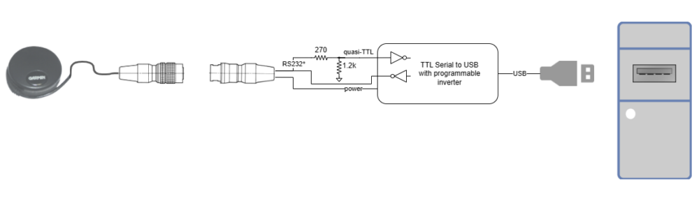
The long-standing favourite amongst Oscilloclock aficionados is the External GPS (Garmin ‘puck’) option. Features include:
- a long cable that allows positioning for best sensitivity
- an inbuilt magnet for attaching to metal beams
- a gorgeous connection system – satisfying haptics and robust locking


Of course, we also have the internal GPS option, where the GPS receiver is mounted on the Control Board itself. This is super nifty, if there is no concern about satellite signal strength where the clock is placed. (This is very rarely an issue. These receivers are extremely sensitive!)

Geolocation
The GPS option allows the Oscilloclock to obtain not just time, but also geolocation information from satellites.
Okay, it’s true that Oscilloclocks are generally placed in a fixed location, so showing the clock’s location on a map might not be very useful…
Think again!
How about an OscilloGlobe, to warm up your long-distance relationship? Plot you and your friend’s Oscilloclocks on a spinning globe, and count down the hours til you meet again…
(Want a closeup of this demo feature? See this video)
Or perhaps you fancy an OscilloWear? A wearable Oscilloclock, sporting a miniature CRT and it’s-only-possible-in-Japan miniaturised circuitry! Complete with GPS.
An OscilloWatch capable of recording your sporting activities? With OscilloMaps that guide you to the nearest Oscilloclock retailer? And of course: the OscilloPhone, or oPhone for short?
Ahh, we could have so much fun making devices that use location data…!
Want even more info on the GPS hardware option? We have a nice support page here: Garmin 18x GPS Puck.
NTP – low-cost & extensible
The Oscilloclock Wave is the glorious device that allows your Oscilloclock to connect to a Wi-Fi router and pull in time from NTP (Network Time Protocol) servers.
It comes in different forms, both external and internal:


The Oscilloclock Wave requires a WiFi connection (and Internet), and some initial configuration – it doesn’t just work straight out of the box, in a standalone way like the GPS option.
However, the Wave has a distinct advantage: it can access various APIs (think: providers of data over the Internet) to pull in and display all kinds of information!
Want to display the current weather on Mars? The latest news? Stock prices ticking madly? All this is technically possible… and can be implemented upon request.
To date, we’ve used this capability in several themed Oscilloclocks: the Astro Clock (pulling in sidereal time from an API) and the AfterShock Clock (pulling in earthquake data).

Not saturated yet? For more on Wifi based synchronisation and various configuration options, see the support page: Oscilloclock Wave.
The No Synchronization option!
Do you want to take your Oscilloclock off-grid? We’ll craft you a unique clock powered by wind, solar, USB-C power bank, or even a hamster wheel. (We can even procure extremely low-power CRTs!) But to go fully off-grid, you won’t want to use GPS or WiFi.
A (more likely!) scenario is simply that signal strength is just too poor. Maybe your clock sits in a basement 3 stories below ground…
For such cases, you can set the time manually in the Time Setting screen. Once set, an on-board quartz oscillator then maintains reasonably good time (in the order of seconds per month). You’ll want to adjust it occasionally!

Decisions, decisions…
Must it be one OR the other? Can’t a gadget lover have their Oscilloclock source data of different types from both GPS and public APIs over the Internet?
Sadly, no – not in the current Control Board revision. This supports only a single interface, which is occupied by either the GPS or the Wave module. (We have multiple input capability on the long to-do list!)
Oscilloclocks are beautiful and entertaining. There’s that warmth of the CRT filament and the brilliance of coloured phosphor excitation, combined with all the features of our digital era.
But above all – they are clocks! Hope you enjoyed this treatise on how time is managed.
If you’re up for the craziness of an Atomic Oscilloclock, or if you want a custom theme using specific API data, let me know! Otherwise, stay tuned!