Let me introduce [Howard]. He loves electronics, has a bunch of old scopes, is obsessed with time accuracy, and happens to be a retired medical doctor.
What do you give a chap like Howard for his birthday?
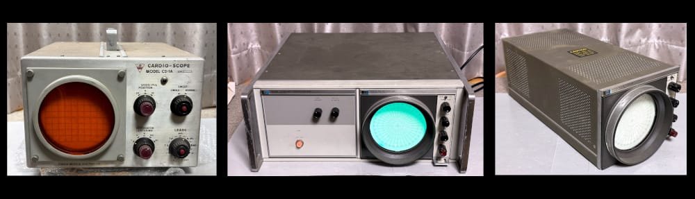
Well, his loving son [Nick] had the answer! He gave his dad the ultimate gift – an Oscilloclock Exo 3KP1 with a custom medical-themed animation!
Hong Kong connection
[Nick] first reached out in February to check out his options. He explained that the family was spread across continents, but would be uniting in Hong Kong for the big birthday event, in June. Four months away!
Could Oscilloclock deliver something glorious and mesmerising for his dad – but in time, and within budget constraints?
Yes and yes!
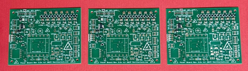
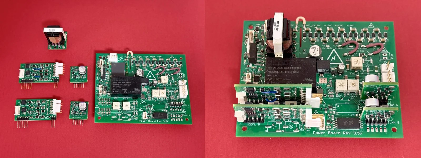
The lab just happened to have a set of fully assembled, older-revision boards just begging for love and attention. And also in stock was a beautiful new cast acrylic Exo case and CRT ring set — with some slight imperfections.
By using these components, we could reduce the time needed to craft the device — and offer a substantial discount to boot!
The clock was ready and shipped a week ahead of time – making sure [Howard] would not go disappointed on his big day.


Perfectly Imperfect
Frequent readers may recognise that your humble Oscilloclock senior engineer has perfectionist tendencies. Any “slight imperfections” come with some concessions.
On the other hand, owners rarely perceive such imperfections as such. They either don’t notice them, or they actively enjoy them as features, making their beloved device just that much more unique.
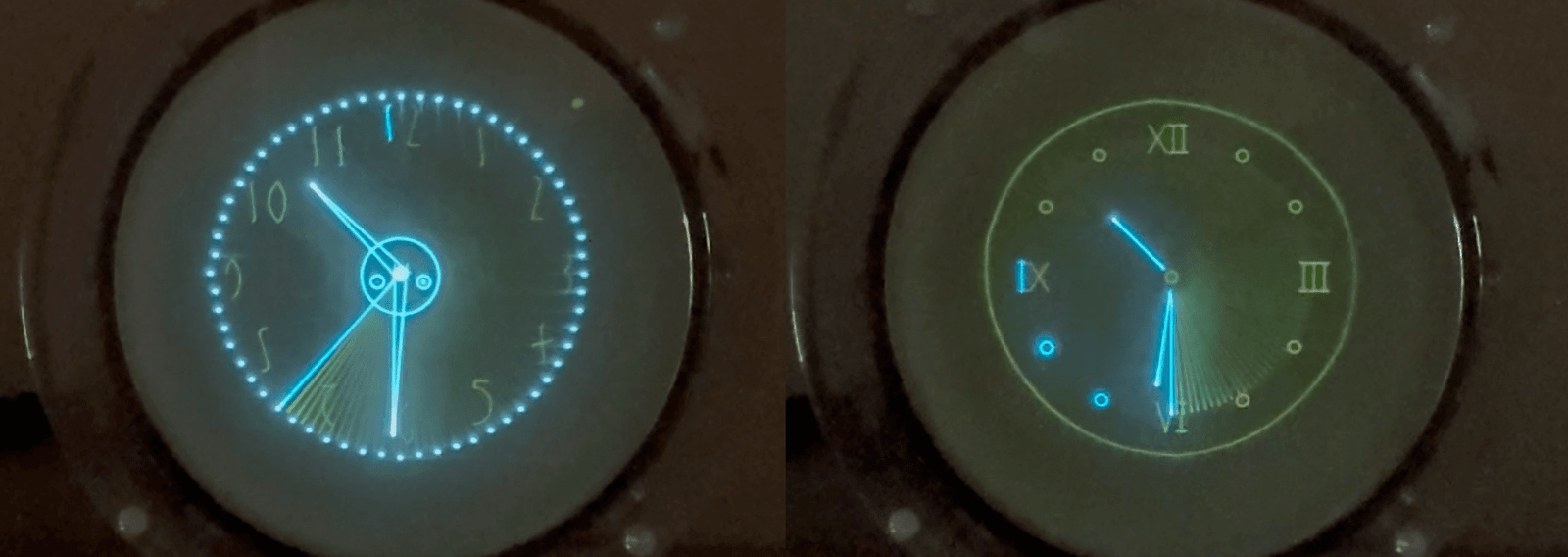
Quiz time! Can YOU spot any blemishes?

Make a wish!
[Howard] no doubt got quite a surprise when he turned on his birthday present and saw it literally light up the room!
No, this was not a pyrotechnic effect made specifically for the occasion! It’s called an inrush current limiter, designed to preserve the longevity of the CRT.
Howard’s device employs what we call “a sacrificial lamb”. In this scheme, a light bulb is used to absorb most of the switch-on current that would otherwise flow directly into the CRT heater. The bulb lights up brilliantly for a time, then dies out as heater resistance increases and current decreases.
Primitive. Low-cost. Yet immensely effective. Brilliant!
Medicine for the Medic
The Oscilloclock Exo is a popular model. But every clock simply must be unique! [Nick] had just the trick in mind, with a request to incorporate the words “What’s Up, Doc?” to reflect his father’s illustrious medical career.
Can do. But we took it a small step further — a simple animation depicting a patient standing behind an X-ray exposure screen!
Post-ceremony
Private birthday celebrations are private; we have no photos to share here of the ecstasy we hope [Howard] felt when, surrounded by [Nick] and his loving family, he unwrapped his birthday gift.
However we do have a photo of the clock in-situ, after the trip back home:

We wish [Howard] many future returns and thank [Nick] for the opportunity to bring joy to the family on their special occasion!
Like what you see? Do YOU have a special person who deserves a special work of art? Let us know. We even gift-wrap!
Like what you read? Every article here has been crafted by hand! While we use AI for idea generation and research, we never use it to write content or even to adjust the tone. What you read comes directly from the heart. Enjoy!