[Mike], a cathode-ray aficionado and a major sponsor of Oscilloclock’s X-Y-Z Core design, reached out earlier in the year with devastating news:
His home, workshop, and all its contents had been completely destroyed in the Palisades Fire (California, U.S.) in January.
We at Oscilloclock are no strangers to earthquakes, typhoons, nuclear meltdowns, and even bear invasions. But we have never witnessed our home, lab, and all surroundings destroyed in a wildfire such as [Mike] experienced:
Homes and neighborhoods devastated by the Palisades Fire. Jan. 14, 2025
What was lost…
[Mike] had been designing and building his own cathode-ray tube based clocks. His focus was on the controller – the microcontroller-based circuit that generates signals telling the CRT’s electron beam where to go, and when to turn on and off. He also designed and built the clock cases himself.
He’d needed help for the high-voltage power supply, deflection amplifiers, and isolated blanking amplifier. These are a little complex (not to mention dangerous), so he’d decided to use the well-matured Oscilloclock X-Y-Z Core product to do all the heavy lifting – so he could just focus on the controller.
And, we’d provided him with a bunch of lovely vintage CRTs.
Putting all these together, Mike had made 4 complete clocks – and wow, they were beautiful!
4 clocks ticking in unison. Blissfully unaware of the disaster awaiting…
Of the four clocks thus constructed, two had gone to [Mike’s] friends.
However, one of the clocks had come to [Mike] for repairs right at the time of the fire.
And just like that – three works of art were lost forever.
The road to recovery
Since the fire, [Mike] has been living in smaller quarters, with no room (and, you can imagine, not much time either) for hobbies.
But we both knew he’d be back into it! And when he reached out in April to discuss getting more XYZ Cores, in anticipation of a fresh year-end re-start, we were overjoyed. To what better cause could a couple Cores contribute?
Two new X-Y-Z Cores, CRTs, cabling, accessories – everything [Mike] needed to get back to work!
[Mike] recently reports that he’s managed to rent a workspace, and will be setting up again from December!
We can’t wait to see what transpires.
We wish the very best to [Mike] and all others affected by disasters, whether natural or inflicted, as they rebuild their lives. And may they never give up in their quest to increase the artistic entropy of our world!
These days, just about everyone has an old oscilloscope lying around. You know, an old, dusty, derelict scope handed down from Grandpa (or Grandma). Well, [Paul] had something even better – an old Tektronix 602 X-Y Monitor! Could an Oscilloclock Control Board drive this vintage beauty? Absolutely. Could I make an aesthetically pleasing case? Definitely. How about time sync via WiFi? Stock standard!
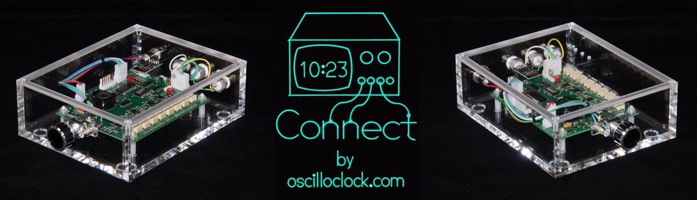
Presenting the Oscilloclock Connect:
Here’s what it looks like plugged in to my fabulous old Tektronix 620 monitor:
And why not have a pair of Connects drive a Tek 601 and 602?
The Build
The main component of the Connect is, of course, a standard Oscilloclock Control Board. As usual, all 121 parts on Paul’s board were individually mounted and soldered by hand. The board then was programmed and underwent rigorous inspection and testing. Finally, the board was cleaned to remove flux and renegade flecks of solder, and sprayed with HV coating for humidity protection and – arguably more importantly – to give it its glorious sheen.
The case was custom-made and professionally machined right here in Japan from 6mm-thick sheets of pure cast acrylic (not extruded). This is an extremely transparent, hard, high grade acrylic – and Oscilloclocks deserve nothing less!
The case was sprayed with a special acrylic cleaner and static protection solution, before fitting the various components. Naturally, every part was cherry-picked, right down to the three BNC connectors – they needed an aesthetically pleasing colour, but they also had to have a shaft long enough to mount through 6mm-thick acrylic!
Finally, the physical interface! The knob was chosen for its perfect finger-fit and delicate aluminium/black tones, which gently contrast with the rest of the unit.
The Compatibility Crisis
Over the years, many folks have observed that the scope at hand has an “X-Y mode”, and asked if they could just ‘plug in’ an Oscilloclock Control Board. “Is it compatible?” Unfortunately, the response has usually been disappointing.
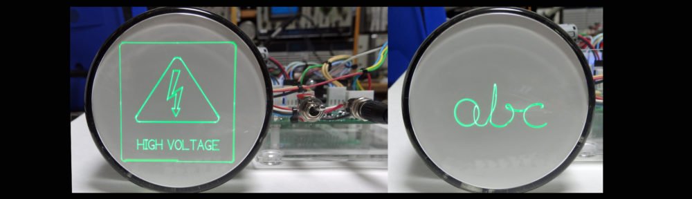
You see, creating figures and characters with Circle Graphics relies on the scope’s ability to turn the beam on and off at split-second intervals. This feature is called a “Z-axis input”. While many scopes from the 80’s and beyond do sport such an input, there are two common limitations:
Limitation 1: AC-coupled Z-axis inputs
Capacitive coupling – effective at isolating the input from cathode potential (-1260V !)
The input is connected to the CRT’s grid or cathode circuit via a capacitor. This is a low-cost, effective way to isolate the (usually) very high negative voltage of the grid circuit from the input.
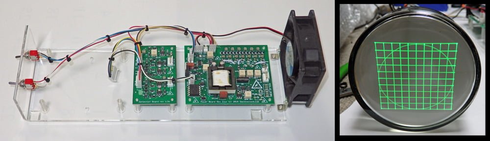
The problem here is that the capacitor, by its very nature, removes the edges from the pulse. The controller is no longer able to control the beam on/off timing, and you end up with uneven blanking across the segments, as shown in the screenshot at right.
Depending on the values of the capacitor and the surrounding resistors, the symptoms may not be severe. However, the best way to resolve this problem (while still keeping the oscilloscope’s original circuit intact) is to insert an isolated DC blanking amplifier directly in series with the grid (or cathode). See the Kikusui 537 Oscilloclock for an example of this.
LIMITATION 2: INSUFFICIENT BLANKING AMPLIFICATION
Most oscilloscopes tend to require at least +5V on the Z-axis input to noticeably blank the beam. The Connect, however, is only capable of delivering +2.5V. It works just fine if you set the scope’s Intensity control very low, but as you increase intensity, the blanking quickly becomes ineffective.
Below we have a beautiful Japanese YEW (Yokogawa Electric Works) 3667 storage scope. The left shot is misleading due to the camera exposure; the displayed image is actually extremely dim. The right shot shows the same* image with the intensity control increased – the image is bright, but there is no blanking!
* Astute readers will observe that the time is significantly different between the two shots. This is a result of the WiFi NTP sync kicking in right in the middle! More (or less) astute readers may also notice that the scope’s trace rotation is not adjusted very well…
Of course, it would be a simple matter to incorporate a pre-amplifier for the Z-axis, which would solve this problem. This will be introduced with the next Control Board revision!
Like what you see?
Nothing brings more joy than connecting this bundle of usefulness into a woefully unused old oscilloscope or X-Y monitor. If this is of interest to you, visit the Availability page for more information, and of course see the Gallery for other unique creations!
Avid followers may have noticed an absence of fresh posts recently… What gives?
I’m happy to report that it’s only because Oscilloclock has been absolutely run off its feet in 2016, producing more crazy CRT based devices than ever before. There just hasn’t been time to do justice to the blog!
The good news here is there are lots of posts in the backlog. Let’s start out with this one:
Yet Another CRT clock fanatic?
I was approached by [Mike], who wanted to design his own CRT clock from scratch, but didn’t want to mess with the high voltage circuitry involved. Could I help out with an X-Y-Z display assembly, and he would do the rest? You bet!
Here is the newly revamped Oscilloclock X-Y-Z Core, shipped out in Q2 2016:
And here is what [Mike] was able to with it, after implementing a totally fresh controller design incorporating Circle Graphics:
[Mike]’s setup – A home-grown controller board, the X-Y-Z Core, and a 3KP1(F) CRT
Here is [Mike’s] story in his own words:
I was thinking of building a Nixie clock, but when I discovered the vector graphic clocks that Aaron and others had built, I knew I needed to build one. I felt comfortable that I could recreate my own version of the digital logic and the low-voltage analog signals, but didn’t really want to tackle the deflection amp or the high voltage circuitry. Buying the Oscilloclock XYZ display solved that problem. Everything arrived as and when promised, and I was beyond impressed by the care and workmanship that’s evident in everything from the boards to the harnesses to the documentation!
I based my controller board on a Cypress PSOC 5LP chip, which allows me to implement all of the digital logic in its on-board programmable logic fabric. The 80MHz 32 bit ARM processor allows me to program 100% in C, which enabled me to create my own version of the software fairly easily. (I tip my hat to those who have done it all in 8-bit assembly!)
Remaining work includes improving my signal quality, which doesn’t yet fully exploit the bandwidth and linearity of the Oscilloclock boards, designing an interesting enclosure, and adding a few software features.
Good luck [Mike] with the rest of your implementation!!!
Key features
This unit is the latest incarnation in a series started in 2015, for a client who needed a custom Head Up Display solution. The boards have undergone through several revisions since then to optimize performance. This particular kit was pre-configured and fully tested to support 3RPx, 3KPx and 3WPx CRT types, and features:
Cathode to deflection voltage of 1875V
Digital blanking (grid modulation), safely isolated at 2.2kV continuous working voltage
Precision deflection amplifier capable of driving +/- 275V with 0.1% linearity
0-5V analog X and Y inputs with 2.5V reference output [Option RS]
TTL/CMOS compatible high-frequency blanking input
Dim/Bright digital input with PWM support
Power Off digital input
Temperature-controlled fan with Failure and Overtemp safety features
CRT rotation coil supply (+/-5V)
CRT heater soft start / inrush current limiting
Oscilloclock X-Y-Z Core set – as shipped
Like what you see?
X-Y-Z displays are cool. But so are my other unique creations! See the Gallery, and stay tuned!
Recently I received a most intriguing request: I was asked to build a self-contained, super-bright X-Y display unit with 3-inch CRT, for use in an “HUD“. Hmm…
Fortunately, I didn’t need to guess any further. As I was once an avid flight simulator enthusiast, I quickly hit upon the correct meaning: Head-Up Display. This is a mechanism that overlays instrumentation or map data onto the view looking forward from the cockpit, so that the pilot doesn’t have to look down to see this information.
Wikipedia has a great introduction to HUDs and their history, but Mike’s Flight Deck has the definitive tome for flight simulator enthusiasts who want to actually build an HUD. According to Mike, the system employs various optical paraphernalia, but at the heart of the mechanism is what lies closest to my own heart – a CRT Display!
An Oscilloclock 3-inch X-Y-Z display unit, optimized for use in an HUD(more…)