By the time you read this post, you must have seen the term “Circle Graphics” in a thousand places across the site.
In fact, “Circle Graphics” is not an official term – I just use it to describe how shapes are drawn on these clocks:
Everything you see on this screen is made up of CIRCLES! Blank out part of a circle and you get an arc. Squish an arc and you get a line. This clock simply draws circles, lines, and arcs of different sizes at various points around the screen. It does it quickly. And it does it very, very well!
The effect of using circles is beautiful – shapes are smooth and precise, with no jagged edges or pixelation.

Making “perfect” circles
I carry on as if it were some incredible new concept or discovery, like the Higgs boson. But in fact, the analog technique of constructing perfect circles, ovals, and lines on a CRT is very, very old. These figures are really part of a class of shapes called Lissajous Figures.
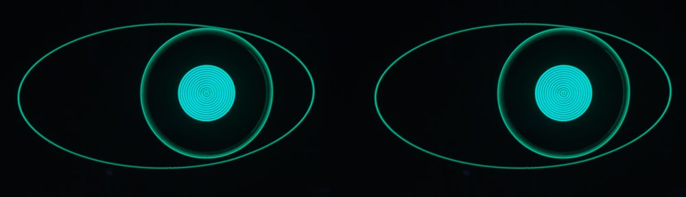
A lissajous figure is what you see on an oscilloscope when you apply a sine wave to the Y axis, and a sine wave to the X axis. Let’s say the sine waves are identical. Then as the spot moves across, it also moves up by the exact same amount. This produces a straight diagonal line, exactly 45 degrees!

Now, let’s take one of the sine waves, and change its phase by 90 degrees; i.e., shift it so that the peaks on one wave line up with the middle-crossing points on the other. You now get a circle! And it’s perfect – round and unblemished.

You can make all kinds of interesting figures by applying waves of different phases, different frequencies, and even different shapes. But in the current Oscilloclock, I only use the two Lissajous figures above – a 45 degree line and a perfect circle. Everything you see on the screen is made up of just these 2 shapes!
Next – Blanking
Drawing the little letter ‘o’ is easy – just one perfect circle. But what about the lowercase ‘c’? It’s a circle, but it has a big chunk taken out of it.
What we need to do is blank the moving beam at just the right time, so that there’s a gap in the circle. That’s right, we just switch the beam off!
In the current Oscilloclock design, blanking can be applied individually to eight 45-degree arcs around the circle. This allows the creation of nice round fonts and show-off designs.

Then – Squishing
This highly technical term describes the final conceptual transformation applied to the circles and lines. We can compress a 45 degree line horizontally or vertically, to create a line of any angle!

Similarly we can compress a circle to make an ellipse, either horizontal or vertical.

The above is a visual analogy really. In practice, there is no real “compression” of a fully drawn circle/line going on. The controller simply adjusts the amplification factor of the X and Y axes in the first place. It’s pre-squished.
Getting the brightness right
Everyone try an experiment. Take a can of spray paint and spray two circles, one very small and one much larger, on a piece of paper. Complete each circle in exactly 1 second. Notice that your arm will be moving much faster in the large circle than on the small circle, to complete the circle in time.
So what do you see? The small circle appears darker than the large circle. This is because your spray can spits out paint at a steady pace – so the larger the area you try to cover in a fixed time, the less coloured your paper appears!

The electron beam in a CRT is similar. Larger shapes will appear lighter (fainter) than smaller ones, because the phosphor excitation from the electron stream is less concentrated. But this is no good!! We want to draw all shapes with exactly the same brightness, regardless of size.
There are a few general methods to solve this problem:
- Change the strength of the electron beam, depending on the size of the shape. This is like using a small nozzle on the spray can for a small circle, and a big nozzle for a large circle.
- Change the time taken to draw the shape once. This is like spraying the circle in 1 second for a small circle, but allowing 5 seconds for a large circle.
- Change the number of times you draw the shape! This is like spraying the circle once for a small circle but 5 times in the same place for a large circle.
The Oscilloclock’s current design uses Method 3. Drawing the shape nn times is something that can be handled purely in code – the software simply gauges roughly how ‘big’ a shape is, and displays it more times for larger sizes. (Yes, the other methods are actually much cooler, but they require some fancy hardware features that are still in the pipeline.)

Putting shapes together
The next exciting post in the series (Circle graphics Part 2) will show how these blanked, squished, and intensity-controlled lines and circles are actually used to draw meaningful things. Don’t miss it – subscribe from the links on the front page!
Particularly keen readers should also visit Sgitheach – Scope Clock II, which has an excellent essay on the theory of operation of circle graphics based scope clocks. The Sgitheach circuit is only the 3rd circle graphics design published on the web so far, and it is truly stunning!