Kikusui Time

Time – the universal constant. Time passes the same for all peoples; rich or poor, busy or idle, inspired or dispirited. And time has certainly passed for Oscilloclock.com since the 2015 Tokyo Maker Faire – the event that just keeps giving!

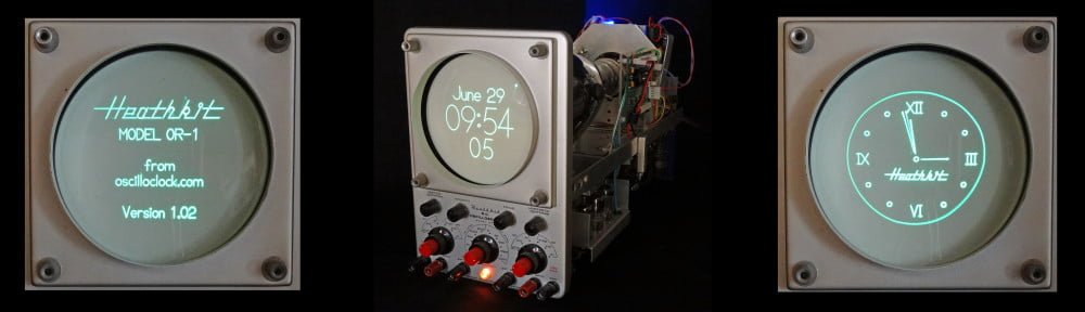
At last, we present the final model from that Faire – the Kikusui 537 Oscilloclock!

Kikusui 537 Oscilloclock

See this in HD, and find more exciting videos on my YouTube channel

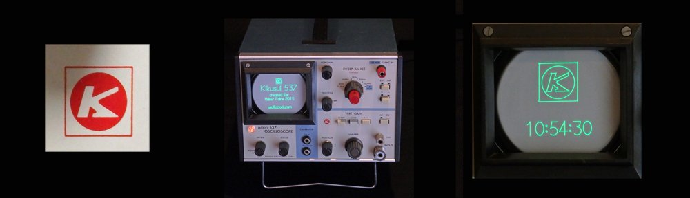
The Kikusui 537 was hand-picked for conversion by the lab’s youngest technician (9 at the time). He chose it for its small size and portability, but also for its cute colour scheme! A dainty red sweep adjustment knob highlights a bright white and black control panel, with a blue case providing overall contrast and visual soothing.

Kikusui 537 Oscilloclock

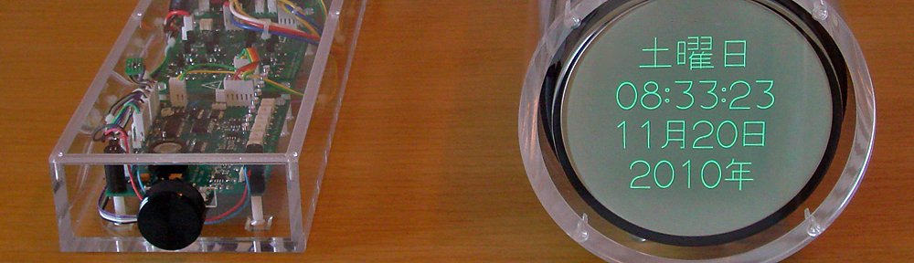
The 537 Oscilloclock’s small size makes it the perfect clock for an office desk, bedside table, or mantle. And since this is a ‘maximum re-use’ conversion, the existing circuit is active and all the front panel controls are fully functional. Fiddle with the image’s size and position to your heart’s content! Switch from XY mode to normal sweep mode, to view raw Oscilloclock signals in real time, as the seconds tick by!

History

The 537 was manufactured by Kikusui Electronics Corp., a major producer of test equipment in Japan since 1951. It was produced in large numbers from 1975 and was extremely popular for its small form factor, solid-state design, 5 MHz bandwidth, and ‘low’ price of 45,000 yen (perhaps USD 1,000 in today’s terms). See the catalogue page (Japanese only) and the operating manual (Japanese and English).

Kikusui Logo

The Kikusui Electronics Corp. logo

Construction highlights

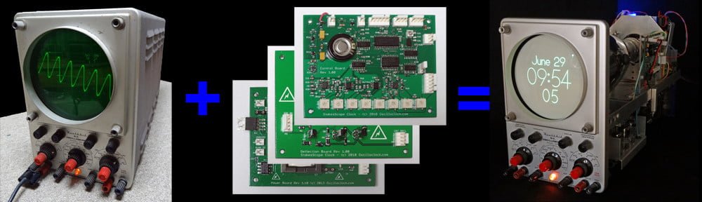
In a previous post, I mentioned there are several general approaches to converting an oscilloscope. Since the Kikusui 537 is fully solid-state (it uses transistors instead of valves/tubes, except for the CRT) and it is only 40 years old, I decided on the maximum re-use, minimal invasion approach. (I really should trademark that term!)

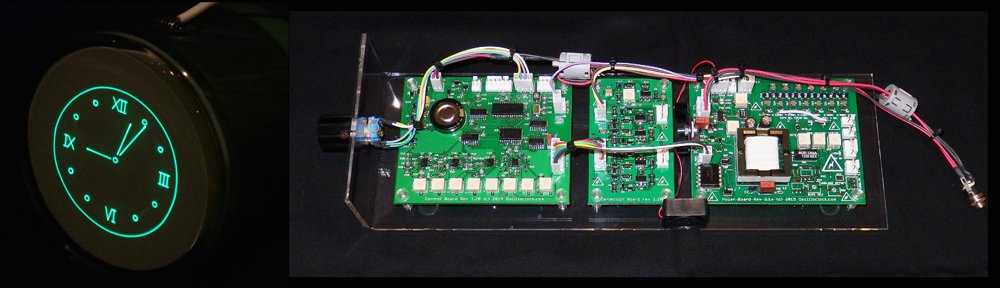
This approach involves tying the Oscilloclock Control Board‘s outputs directly into the existing X and Y amplifier circuits. This was easy to do in the 537!

Kikusui 537 Oscilloclock - inside top

Oscilloclock Control Board mounted in the 537

However, as discussed in the Circle Graphics post, we also need to be able to blank the beam at extremely precise intervals. Sadly, the 537 (like nearly all oscilloscopes of this vintage) does NOT have a convenient DC pulse-tolerant Z-axis input. I therefore installed an Oscilloclock Power Board, partially populated to serve as an isolated blanking amplifier, in series with the grid.

Partially populated Oscilloclock Power Board

Partially populated Oscilloclock Power Board

Finally, an Oscilloclock Supply Board was needed to power the other boards.

An Oscilloclock Supply Board is also nestled in there!

An Oscilloclock Supply Board is also nestled in there!

Mounting the Control

What better place to fit the rotary encoder, than on the beautiful red sweep frequency adjustment knob that my junior technician liked so much! Here’s the general story:

Kikusui 537 Oscilloclock - control (original)

Sweep adjust control in its original state

After removing the potentiometer

After removing the potentiometer

The encoder, after hacking with a hacksaw!

The encoder, after hacking with a hacksaw!

Kikusui 537 Oscilloclock - control mounted

Voila – sweep knob now drives the rotary encoder!


Like what you see?

One of the two Kikusui 537 Oscilloclocks crafted for the Maker Faire is still available for the special person with a soft spot for a krazy kikusui klock. Visit the Availability page for more information, and of course see the Gallery for other unique creations!

The Oscilloclock Core

Over the years, folks out there have reached out to me with all sorts of crazy ideas about cases and housings for scope clocks and custom CRT displays. Here are some interesting examples:

  • The console of a vintage pipe organ
  • An ancient grandfather clock
  • A cylindrical case made of some exotic wood
  • A “cathedral” style vintage radio

Essentially, these people wanted just the innards of an Oscilloclock, which they would build into their own case. Could I help out?

Absolutely! For people who want to roll their own cases, and who have experience handling high voltage electronics and CRTs, I occasionally prepare custom board sets that are lovingly hand-assembled, tested, and tweaked for optimum performance with a given CRT. Here we go:

The Oscilloclock Core

Oscilloclock Core, hand-crafted in 2015 for a discerning customer in Germany

An Oscilloclock Core, hand-crafted in 2015 for a discerning customer in Germany


The standard Oscilloclock Core layout, on a test acrylic mounting

The standard Oscilloclock Core layout, on a test acrylic mounting

I supplied this particular unit with an 8SJ42J Chinese-made CRT, just for testing purposes. This is a 3″ PDA tube with a highly restrictive rectangular viewing area, but the customer found it just great for checking things out!

Oscilloclock Core - complete set for 8SJ42J - 03Oscilloclock Core - complete set for 8SJ42J - 06
Oscilloclock Core - complete set for 8SJ42J - 02

What comes with it?

Here’s what’s comprises the typical Oscilloclock Core:

  • 1 x Fully assembled and programmed Control Board (optional on-board GPS)
  • 1 x Fully assembled Deflection Board (latest ultra-linear revision)
  • 1 x Fully assembled Power Board optimised for a given CRT (latest revision with options: onboard high-bandwidth blanking amplifier, rotation coil supply, auto fan speed control, unblanking plate modulation, and isolated bright/dim input)
  • 1 x Fully assembled CRT Board (optional; an external blanking amplifier recommended when the CRT cable is longer than 50cm)
  • 1 x Rotary encoder
  • 1 x Worldwide 9V power supply (high quality wall wort unit, commercial ratings)
  • 1 x Garmin GPS unit with 5m cable; wired to board-side connector (not required for onboard GPS)
  • 1 x Set of standard inter-board and CRT harnesses for testing and reference (10kV/3kV silicone melt-proof used for HV cables, other LV cabling also heat-resistant)
  • 1 x Cast acrylic test mounting assembly, fitted with the boards, ready for testing out-of-the-box with your CRT
  • 1 x Ceramic adjustment screwdriver
  • Service documentation (schematics, board layouts, complete Digikey BOMs, harness specs)
  • All components are latest available types sourced within the last 6 months, 0.1% or 1% tolerance resistors, minimum 2 x rated working voltage capacitors, all lovingly hand-mounted by myself
  • All boards sprayed with HV lacquer for moisture and arcing protection
  • 2-week satisfaction guarantee. But no long-term warranty on board-only purchases

Naturally, the lengths of all harnesses and inter-board cabling can be customized according to the owner’s requirements. And there is also an Oscilloclock Core Cube arrangement, where the boards are stacked to reduce the length and width of the overall unit.

What CRTs does it support?

The Power Board and Deflection Board are increasingly flexible with each revision, but I insist on performing all configuration of the Core here in my lab. This allows me to tweak for maximum performance, and provide a proper satisfaction guarantee.

Typically I work with the owner to recommend a CRT based on preferences such as size, colour, and aesthetics. However in cases where the owner already has a CRT in mind, and I don’t have the particular CRT or a close equivalent, I ask the owner to send me one to test against. Or, I simply procure one; after all, one can never have too many CRTs!  (Though my better half does not agree…)

The current Oscilloclock Core board revisions meet the following operating parameters:

  • Maximum cathode to deflection voltage of 2175V
  • Maximum accelerator voltage of 3525V for PDA type CRTs
  • 6.3V heater, max 0.7A
  • Support for “Deflection Blanking” CRTs (see treatise here)
  • CRT rotation coil supply (+/-5V)
  • Precision deflection amplifier capable of driving +/- 275V with 0.1% linearity

Like what you see?

Check out the Availability page for more information, and of course see the Gallery for some unique CRT creations – many with an Oscilloclock Core at their heart!

Oscilloclock at Maker Faire Tokyo!

Summer is over! But even as cool weather sets in, the Oscilloclock.com lab is smoking hot, preparing for…

Maker Faire Tokyo 2013

Visit the Oscilloclock.com booth, and check out the luxury 2013 edition Model 1S – to be announced in this blog at end October. One unit will go on sale at the event!

Continue reading

Making the Heathkit Oscilloclock

Last month’s post about the Heathkit Oscilloclock generated tremendous interest, and I’ve heard from several folks keen to try their hand at preserving their own beloved instruments.

… so let’s take a brief look at what was involved in the Heathkit OR-1 conversion!

Heathkit Oscilloclock - inside

Approaches to conversion…

There are many approaches to retrofitting a scope into an Oscilloclock, but it really boils down to how much of the original circuit you want to re-use, vs. what you will bypass with Oscilloclock boards.

Continue reading

A Heathkit Oscilloclock!

Anyone familiar with Heathkit®?

From 1947 to 1992, the U.S. based Heath Company produced electronic kits for everything you can imagine: radios, TVs, computers, robots, ham gear, and electronic test equipment. Yes, you guessed it – they also produced kits for oscilloscopes!

My Grandpa purchased one such scope, the Heathkit OR-1, around 1960. He wanted to kick off a new career in electronics repair, and the ‘build-your-own-equipment’ approach to training was in full bloom at the time. Also, since this was before the era of cheap overseas manufacturing, he could buy a Heathkit far cheaper than an assembled scope.

Heathkit OR-1 manual - a work of art

Heathkit OR-1 manual – a work of art

Unfortunately, Grandpa’s electronics career never really took off. But decades later, he introduced me to his gorgeous oscilloscope, and boy – did that kick MY career off! Much later, the OR-1 came to live with me. (You can read a bit more about my affinity for this scope in my History page.)

The problem is, I have too many oscilloscopes. But I don’t have enough Oscilloclocks. What more fitting way to keep Grandpa’s legacy alive, than to retrofit his Heathkit?

Heathkit OR-1 Oscilloclock

Heathkit Oscilloclock - Splash and Clock

Special features

Continue reading