Over the years, folks out there have reached out to me with all sorts of crazy ideas about cases and housings for scope clocks and custom CRT displays. Here are some interesting examples:
- The console of a vintage pipe organ
- An ancient grandfather clock
- A cylindrical case made of some exotic wood
- A “cathedral” style vintage radio
Essentially, these people wanted just the innards of an Oscilloclock, which they would build into their own case. Could I help out?
Absolutely! For people who want to roll their own cases, and who have experience handling high voltage electronics and CRTs, I occasionally prepare custom board sets that are lovingly hand-assembled, tested, and tweaked for optimum performance with a given CRT. Here we go:
The Oscilloclock Core


I supplied this particular unit with an 8SJ42J Chinese-made CRT, just for testing purposes. This is a 3″ PDA tube with a highly restrictive rectangular viewing area, but the customer found it just great for checking things out!


What comes with it?
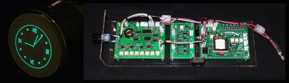
Here’s what’s comprises the typical Oscilloclock Core:
- 1 x Fully assembled and programmed Control Board (optional on-board GPS)
- 1 x Fully assembled Deflection Board (latest ultra-linear revision)
- 1 x Fully assembled Power Board optimised for a given CRT (latest revision with options: onboard high-bandwidth blanking amplifier, rotation coil supply, auto fan speed control, unblanking plate modulation, and isolated bright/dim input)
- 1 x Fully assembled CRT Board (optional; an external blanking amplifier recommended when the CRT cable is longer than 50cm)
- 1 x Rotary encoder
- 1 x Worldwide 9V power supply (high quality wall wort unit, commercial ratings)
- 1 x Garmin GPS unit with 5m cable; wired to board-side connector (not required for onboard GPS)
- 1 x Set of standard inter-board and CRT harnesses for testing and reference (10kV/3kV silicone melt-proof used for HV cables, other LV cabling also heat-resistant)
- 1 x Cast acrylic test mounting assembly, fitted with the boards, ready for testing out-of-the-box with your CRT
- 1 x Ceramic adjustment screwdriver
- Service documentation (schematics, board layouts, complete Digikey BOMs, harness specs)
- All components are latest available types sourced within the last 6 months, 0.1% or 1% tolerance resistors, minimum 2 x rated working voltage capacitors, all lovingly hand-mounted by myself
- All boards sprayed with HV lacquer for moisture and arcing protection
- 2-week satisfaction guarantee. But no long-term warranty on board-only purchases
Naturally, the lengths of all harnesses and inter-board cabling can be customized according to the owner’s requirements. And there is also an Oscilloclock Core Cube arrangement, where the boards are stacked to reduce the length and width of the overall unit.
What CRTs does it support?
The Power Board and Deflection Board are increasingly flexible with each revision, but I insist on performing all configuration of the Core here in my lab. This allows me to tweak for maximum performance, and provide a proper satisfaction guarantee.
Typically I work with the owner to recommend a CRT based on preferences such as size, colour, and aesthetics. However in cases where the owner already has a CRT in mind, and I don’t have the particular CRT or a close equivalent, I ask the owner to send me one to test against. Or, I simply procure one; after all, one can never have too many CRTs! (Though my better half does not agree…)
The current Oscilloclock Core board revisions meet the following operating parameters:
- Maximum cathode to deflection voltage of 2175V
- Maximum accelerator voltage of 3525V for PDA type CRTs
- 6.3V heater, max 0.7A
- Support for “Deflection Blanking” CRTs (see treatise here)
- CRT rotation coil supply (+/-5V)
- Precision deflection amplifier capable of driving +/- 275V with 0.1% linearity
Like what you see?
Check out the Availability page for more information, and of course see the Gallery for some unique CRT creations – many with an Oscilloclock Core at their heart!