Recently, [Justin] asked: Can his beautiful Tektronix 606 XY monitor be made to work as a computer display?
And even more recently, [TJ] explained he has a plethora of Tektronix devices, and asked how he might put them to use…

Well, “putting to use” is precisely what we do here at Oscilloclock! And one option, indeed, is to hook the target device up to a modern-day PC and use it as a computer monitor.
Time for an update on the Oscilloclock VGA Core and its variants!
Shades of Grey Green
Avid readers may recall these previous posts about making SVGA and XVGA displays from vintage oscilloscope CRTs:


Truly dedicated readers may even recall that the solutions presented drive the CRT directly, completely bypassing any internal circuitry of the host device. And, that there were limitations in the current design; the most serious being binary blanking, where the beam is switched either on or off. There were no shades of grey.
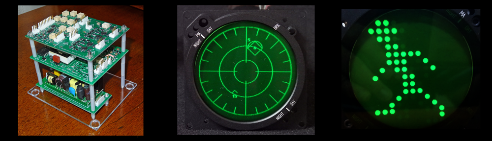
Inspired by [Justin], we experimented connecting the Oscilloclock VGA Bare (a barebones VGA interface board) to our lab’s Tektronix 620 XY monitor. This bad boy has an analog Z axis (intensity) input, meaning that we can theoretically have shades of grey… er, green.
And the result? A pretty decent PC display!


Doomy Demo
Ever wanted to play classic Doom on an old green screen? Here we go!
Yes – the display is horizontally inverted. The VGA Bare currently does not support flipping the X and Y signals.
This unintended challenge makes playing Doom exceptionally difficult!
Matrix Masterpiece
Who could resist displaying digital rain (Matrix code) on an old Tek display?
While working on this demo, I learned more about Matrix code – and that it includes Japanese characters scanned from the creator’s wife’s cookbook. Wow, I thought those raindrops looked awfully familiar!
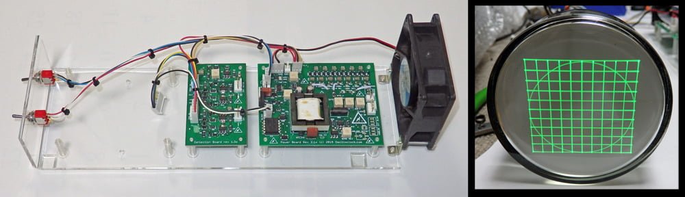
The Setup
Not a bad result! And the hardware setup was simple.
- PC
- HDMI to VGA adapter cable
- Oscilloclock VGA Bare
- BNC cables and connectors
- A few resistors
- Power pack


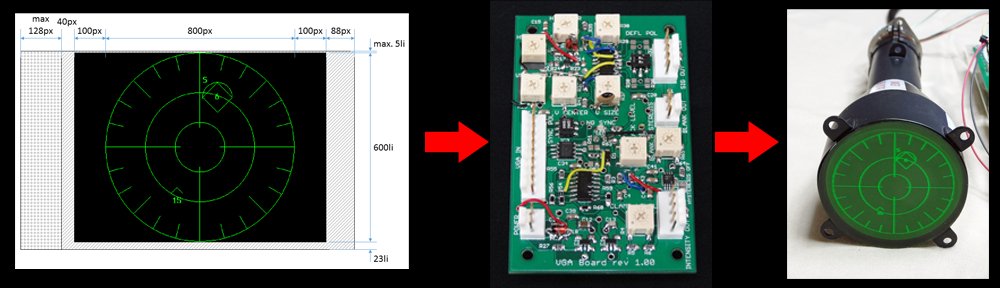
As always, nothing is perfect! A few tricks were needed to make the experiment a success:
- The VGA Bare circuit needed a few minor improvements, to better support official SVGA and XVGA timing standards
- A crude level adjuster (resistive divider network) was needed between the analog intensity output and the Tek’s Z axis input
- The PC display resolution needed to be set to SVGA (800 x 600) or XVGA (1024 x 768), to give maximum clarity
- A high-contrast theme was selected, to greatly improve display contrast
What’s next?
With the successful close of this proof-of-concept, [Justin] and [TJ] now have another clear option to make use of their vintage test equipment: a VGA Bare ready to mount inside their device, or a beautifully encased VGA Connect (à la Oscilloclock Connect).
But to make this truly production-worthy, a few improvements are needed:
- Output voltage level adjustments, fully independent for X, Y, Z
- A higher-voltage Z amplifier
- Independently invertable X and Y signals
- Reduction in the ‘ghosting’ or ‘ringing’ effects currently observed
- Improved contrast and avoidance of ‘washout’ seen between pixels
- Digital HDMI input !
… all added to Oscilloclock’s ever-growing backlog of things to do!
Do you want to play your favourite classic game on your old XY monitor? Do you want to stack 10 oscilloscopes on your shelf and have them all showing Matrix code? Or put your Grandpa’s old scope on your desk at work and have it display your Outlook calendar?
Our mantra makes it possible: Just. Because. We. Can.