We prepared an exclusive catalogue with select devices in our stock that would meet the large-screen requirement.
~Brian~ immediately spotted the model he wanted!
It seems the finish of this unit reminded him of military devices his grandfather had once owned. Well, your senior Oscilloclock engineer certainly knows the influence a grandfather can have. A great choice, for all the right reasons!
Fast forward to May 2026 — and the labour of love was complete!
A true labour of love – the Kikusui MC-120 Oscilloclock!
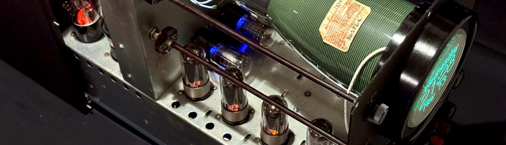
Oh, my! Just look at those internals!
We discovered at an early stage that the MC-120’s chassis slides out from the case relatively easily. Could we reduce friction enough that ~Brian~ could easily pull the unit open any time he wanted to gaze at the internals?
ABSOLUTELY we could, and we did!
But we took it one step further, by installing LED lighting into the tubes — simulating the look and feel of the original ‘scope in actual operation!
Thanks to Teflon-coated slide guides, the chassis can be easily extracted!… and extracted fully, you even enjoy the ST (shoulder-shaped glass) tubes in the rear!LEDs — specifically selected to reproduce the colours of the original tubes when lit. So soothing!Don’t forget — CRTs can also be incredibly beautiful!
This is perfect timing(!), as 2026 marks the 100th anniversary of the marvelous Metropolis movie by Fritz Lang!
Screens are kept simple, but they bring a lot of pleasure!
Latched on to Panels
Avid readers may remember that we LOVE oscilloscopes that have panels. Especially those with latches. Check out our posts here, here, and here! We can’t resist playing with them, and we are absolutely not alone in this fetish.
Well, this MC-120 also has a lovely latch panel in the rear. We’re not using it for anything. But look carefully! You can just see one of the LED-lit tubes inside…
Wave for the camera!
How do Oscilloclocks keep accurate time? We’ve written a full treatise before about the various options available. For the MC-120, we chose to install a custom Oscilloclock Wave board enabling NTP time synchronization over WiFi.
This board has been designed specifically to replace the no-longer-necessary fuse box in the rear of the scope:
It’s a clock, after all — it has to stay accurate!
Wait – reduce Weight!
The Kikusui MC-120 in its original form weighed at least 20kg (45 lbs). ~Brian~ accepted our pragmatic suggestion to strip out the original power transformer and choke coil, bringing the weight of the entire unit down significantly.
This weight loss helped greatly to reduce force required to pull out the chassis. But equally importantly, it halved the shipping costs!
During the build, we also stripped out a number of other components. But don’t worry, most will not go to waste. Tube amp enthusiasts love transformers!!
These won’t be wasted — audiophiles await!
Hang on, where’s all the circuitry??
~Brian~ wished to retain the orginal looks above the chassis, so we mounted all Oscilloclock circuitry underneath!
Like what you see?
Actually, we hope you don’t like this specific Kikusui MC-120 too much, because it’s unlikely that we will ever come across another one! But never fear; we have other devices aplenty. We must have something special for you. And we can do some special things with it. Just let us know your ideas.
Recently, [Justin] asked: Can his beautiful Tektronix 606 XY monitor be made to work as a computer display?
And even more recently, [TJ] explained he has a plethora of Tektronix devices, and asked how he might put them to use…
So lovely… but what can you DO with it?
Well, “putting to use” is precisely what we do here at Oscilloclock! And one option, indeed, is to hook the target device up to a modern-day PC and use it as a computer monitor.
Time for an update on the Oscilloclock VGA Core and its variants!
Shades of Grey Green
Avid readers may recall these previous posts about making SVGA and XVGA displays from vintage oscilloscope CRTs:
Truly dedicated readers may even recall that the solutions presented drive the CRT directly, completely bypassing any internal circuitry of the host device. And, that there were limitations in the current design; the most serious being binary blanking, where the beam is switched either on or off. There were no shades of grey.
This Running Man needs no shades!
Inspired by [Justin], we experimented connecting the Oscilloclock VGA Bare (a barebones VGA interface board) to our lab’s Tektronix 620 XY monitor. This bad boy has an analog Z axis (intensity) input, meaning that we can theoretically have shades of grey… er, green.
And the result? A pretty decent PC display!
A recent post, as displayed on the Tektronix 620. (Yes – I know it’s upside down)Here’s what it looked like on the laptop’s display
Doomy Demo
Ever wanted to play classic Doom on an old green screen? Here we go!
This Tek 620 is no longer doomed – it’s been Doomed!
Yes – the display is horizontally inverted. The VGA Bare currently does not support flipping the X and Y signals.
This unintended challenge makes playing Doom exceptionally difficult!
Matrix Masterpiece
Who could resist displaying digital rain (Matrix code) on an old Tek display?
Matrix code, as generated by tmatrix. Note it’s horizontally inverted
While working on this demo, I learned more about Matrix code – and that it includes Japanese characters scanned from the creator’s wife’s cookbook. Wow, I thought those raindrops looked awfully familiar!
The Setup
Not a bad result! And the hardware setup was simple.
PC
HDMI to VGA adapter cable
Oscilloclock VGA Bare
BNC cables and connectors
A few resistors
Power pack
As always, nothing is perfect! A few tricks were needed to make the experiment a success:
The VGA Bare circuit needed a few minor improvements, to better support official SVGA and XVGA timing standards
A crude level adjuster (resistive divider network) was needed between the analog intensity output and the Tek’s Z axis input
The PC display resolution needed to be set to SVGA (800 x 600) or XVGA (1024 x 768), to give maximum clarity
A high-contrast theme was selected, to greatly improve display contrast
What’s next?
With the successful close of this proof-of-concept, [Justin] and [TJ] now have another clear option to make use of their vintage test equipment: a VGA Bare ready to mount inside their device, or a beautifully encased VGA Connect (à la Oscilloclock Connect).
But to make this truly production-worthy, a few improvements are needed:
Output voltage level adjustments, fully independent for X, Y, Z
A higher-voltage Z amplifier
Independently invertable X and Y signals
Reduction in the ‘ghosting’ or ‘ringing’ effects currently observed
Improved contrast and avoidance of ‘washout’ seen between pixels
Digital HDMI input !
… all added to Oscilloclock’s ever-growing backlog of things to do!
Do you want to play your favourite classic game on your old XY monitor? Do you want to stack 10 oscilloscopes on your shelf and have them all showing Matrix code? Or put your Grandpa’s old scope on your desk at work and have it display your Outlook calendar?
Our mantra makes it possible: Just. Because. We. Can.
Here at the Oscilloclock lab there’s nothing more pleasurable than helping put a cherished vintage oscilloscope back into action. A new lease on life!
That’s why when [Chris] reached out about his early 1970’s Conar 255 oscilloscope, wanting to convert it into a Vectrex gaming machine, we were naturally excited!
The original Vectrex was an incredibly cool device. Instead of the pixelated, blocky graphics of the time (anyone remember Pac-Man?), the system used vector graphics to draw smooth line-art images. Each vector was a straight line, or a smooth arc, connecting point A to B. Vectrex games were true works of art, and the original hardware is quite rare (and $$$)!
Well, [Chris] caught the vector graphics bug. But he decided to build a Scopetrex – a hardware emulator that allows you to run Vectrex games on an oscilloscope! He would theoretically just connect this to the Conar 255’s existing X, Y, and Z (blanking) inputs.
We like this “minimum invasion, maximum re-use” approach. We’ve gone down this route numerous times to craft Oscilloclocks out of still-usable hardware. (The alternative? Install a full set of modern boards that drive the CRT directly.)
Sample specimens of “minimum invasion, maximum re-use”
[Chris] got down to planning. He could interface the X and Y inputs easily. But he faced a problem with the Z (blanking, or intensity modulation) signal, which instructs the scope when to turn the beam on and off:
The Scopetrex outputs a 5V DCdigitalblanking pulse.
The Conar requires at least 20V peak-to-peak blanking signal – and employs analog AC coupling.
We’ve solved this mismatch problem before using various non-standard Oscilloclock board setups and complex hook-ins to the existing circuits. Always on a case-by-case basis, always unique.
But now, at last, it was time to standardise the process. To make it easy. To adapt any vintage oscilloscope for digital blanking from a microcontroller! We proudly announce the next member of the Core family: The Z Core!
The Z Core (in this case, a Z Core 2 Ex) …
… joins the Oscilloclock Core family!
How to install it
Believe it or not, the minimal installation requires just 3 steps. For almost any oscilloscope! The Z Core effectively sits in series between your device’s blanking supply and the CRT grid.
Snip the wire connecting to CRT grid.
Connect the orange wire from the Z Core to the circuit side of the cut wire.
Connect the green/yellow wire to the CRT grid.
Snip.Connect!
Visit the Z Core Support Page for lots more detail, including the obligatory warnings about high voltage. There are also details on how to connect the Z Core to your controller, detailed specifications, and some fun Q&A to help answer your most burning questions!
The Z Core 2 Ex!
We’ve wanted to develop a dedicated, built-for-purpose Z Core product for a very long time. This would consist of a single, miniaturised, low-power board called (ingeniously) a “Z Core Board”, and a few harnesses.
But [Chris] didn’t want to wait for Oscilloclock labs to work through its ever-growing bucket list. Could we deliver within 2024?
Yes!
In past retrofits such as the Kikusui 537, we’ve taken spare boards that were originally designed for fully-featured Oscilloclocks, and partially populated them with only the necessary components to serve the blanking purpose.
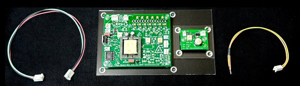
Partially populated Oscilloclock Power Board
For [Chris], we found an almost fully-populated new-old-stock Power Board v2.27 and compatible CRT Board v1.21 lying around, just dying to be used and loved by someone. Older revision boards do tend to be set aside, as folks want the latest and greatest.
With just a few minor modifications, this assembly shipped – and is now branded as the Z Core 2 Ex. The “2” refers to the Power Board’s major revision, and the “Ex” stands for “external blanking amplifier” (the function of the CRT Board). The Power Board rev2.2x series boasts an on-board blanking amplifier, but this section wasn’t already populated. What a great opportunity to use up a stock CRT Board!
[Chris] will be happy. And we’ll keep up this spirit of minimising waste. You’ll see some other Z Core assemblies popping up in future: a Z Core 1 Ex, a Z Core 2, and potential variations of Z Core 3’s.
And finally, one day, a genuine dedicated Z Core will be born!
Why your scope needs a Z Core …
Many old oscilloscopes simply don’t have any input for Z blanking, Z axis, intensity modulation, or cathode modulation. (Look carefully – it goes by many names!) Or, the input may be there, but it’s not compatible with a microcontroller. Why couldn’t the designers offer a decent interface?
Well, it all has to do with high voltage! To get there, let’s cover how CRTs work in just three short sections:
Gun
A cathode-ray tube (CRT) has an electron gun that shoots electrons at the phosphor molecules on the screen. The electron beam is deflected by putting positive and negative voltages into electrodes placed in the CRT’s neck, and this is how patterns are drawn on the screen.
This is how a CRT works. It’s awesome.
But the electron beam has to be turned on and off, to break the pattern and make meaningful images on screen. This is known as blanking.
Blanking
Oscilloscopes, particularly, have to blank the beam when it goes back (retrace), from the right to the left again. If there were no blanking, you’d see a retrace line – wickedly cool for us artists, but devastatingly distracting for engineers who want to focus on the waveform itself!
Retrace lines – arty but not desirable
Oscilloclocks also rely on blanking. In Circle Graphics, where all figures are composed of lines and circles, blanking is crucial to creating meaningful segments. For example, a “C” is readily created from an ellipse “O”, simply by blanking the beam at just the right place!
A blanking pulse kills the beam to get a ‘C’
Grid
CRTs are designed for blanking. There’s a valve-like electrode called a grid that sits inside the gun, just in front of the cathode where the electrons are spat out. If you inject a negative voltage into the grid (compared to the cathode), it repels those electron babies and sends them back where they came from. They don’t bombard the screen, and no more light is emitted. Blanking in action!
Titillating! Electron field density is reduced when a negative voltage is applied to the grid!
A fuller explanation – from The Bible
The bible
A change in grid voltage influences the field distribution of the first lens, and in so doing controls the emission from the cathode. For any fixed value of voltage applied to anode 1, it influences the number of electrons which pass through the cross-over point. Let us see how this comes about. In Fig. 5-17 is shown the field distribution in the first lens for two values of grid bias, O and -30 volts, and a fixed value of voltage on the plate.? It is clearly evident that with zero bias, the area adjacent to the cathode, between the cathode and the control-grid aperture, has a comparatively high positive potential as the consequence of the field between the control grid and the first anode. Under such conditions of zero grid voltage, it has been found that the area of the cathode which is emitting corresponds approximately to a projection of the area of the grid aperture; the maximum number of electrons are passing through the grid opening and the beam-current density is high.
When the control grid is made negative by an increase in the bias, —30 volts in the illustration, the field distribution in the vicinity of the cathode is altered so that only the center of the emitting surface is behaving as an emitter. The other areas are influenced by the space charge and effectively are not emitting. The result is a reduction in beam density and several other related effects.
High voltage
So – back to the high voltage aspect. The cathode and grid are usually about 2kV (that’s right – 2,000 volts!) negative compared to the rest of the circuits. If you connected an external input signal directly to the grid, something would fry.
Old-school oscilloscope designers took a very easy (read: cheap) solution: they stuck a high voltage capacitor between the grid (or cathode) and the external signal. This is called AC coupling because the capacitor blocks the DC voltage (2kV), and only couples through the AC (the fluctuating blanking) component of the signal.
AC coupled external intensity modulation in the Conar 255 (L) and the Trio CS-1554 (R)
This method of intensity modulation was fine for the regular, repeating signals observed in old TVs and radios. But it isn’t what [Chris], or so many millions out there like him, needs! They need to send through an irregular, sometimes not-fluctuating-at-all (i.e., DC) signal. They need DC coupling! And it has to be isolated – standing off more than 2kV!
And there’s another voltage related problem: the grid has to go substantially negative with respect to the cathode, in order to completely block the electron flow. We’re talking 20-50V typically. This is not a voltage that a modern microcontroller board will deliver! This requires an amplifier.
Summing it up
So that’s it! Just three(?) words. We need an isolated DC-coupled amplifier. And it needs 2kV isolation with a 10x amplification factor.
Welcome to the Z Core!
Demo
No assembly can leave our lab without being fully tested, and without a demonstration to ensure the customer’s utmost satisfaction. Here’s how the demo went:
The host device: Trio CS-1554
This venerable Trio (also branded as Kenwood) hails from around the same era as the Conar 255. It was attractive, had fairly good specifications, and a low(-ish) price tag, making it very popular both in Japan and overseas. Documentation is freely available and… more importantly, I had one lying around!
Look carefully – it’s bulging and leaking!
Of course this device is full of high voltage oil capacitors. These were effective in their day, but they break down over time, and things get very nasty. One particular HV capacitor in this unit was overheating to the point that the metal case had warped, and oil was even leaking out! Ick.
A few modern-day capacitors hacked together replaced the leaky unit and saved the day. Onwards!
Connect Z Core outputs to Trio CRT grid and grid circuit (as shown in earlier section)
Incompatibility! The Trio’s horizontal input seemed to want 10V peak-to-peak for maximum deflection (this is way off its original specs of 250mV/cm. I think it’s broken!) The Connect by default has only a 3V peak-to-peak output signal. The image is going to be small… ↩︎
Trickery! The Connect by default is designed for a display device with a high-impedance Z input. The Z Core 2 Ex has a low-impedance input and 15mA drain at 5V. A temporary mod was needed in the Connect – which was promptly reversed after the test. ↩︎
The result? A relatively clean image, albeit small! But the blanking works well. [Chris] was okay with the jagged edges and other blemishes; these are attributable to the Trio’s rough condition.
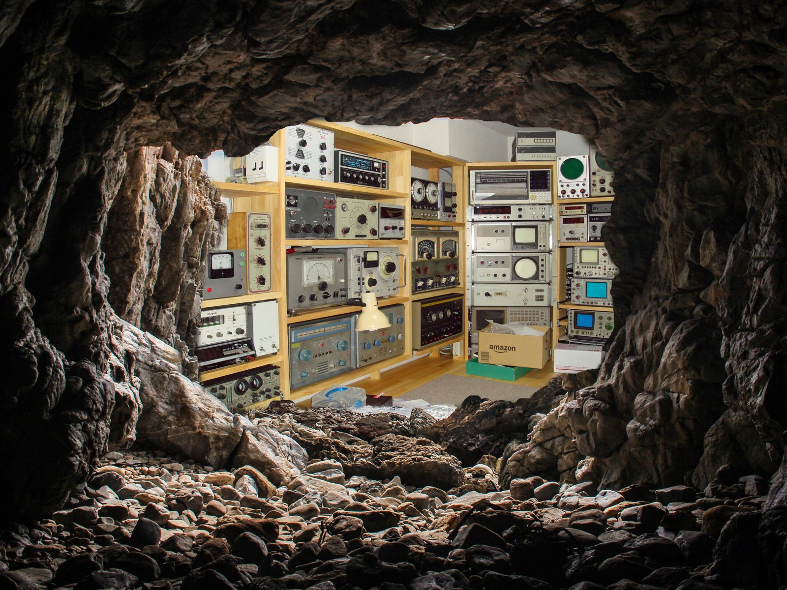
Performance testing
The Oscilloclock cave is not a precision testing laboratory. But we do have a significant collection of equipment, and every piece plays its part. In this case, we deployed a Hewlett Packard 1901A Pulse Generator.
Choosing amongst a plethora of delightful old oscilloscopes, we stayed with the HP theme and used a venerable but still digital HP54615B.
Set output to 5V and connect to the Z Core’s input
Connect a 20pF capacitor across the Z Core’s output, via the standard 200mm 22AWG harness
Connect Ch1 of the scope to the input, Ch2 of the scope to the output
Results
Measurement
Assembly: Z Core 2 Ex
Waveform base voltage
-46V
Rise time
130 ±10 ns
Fall time
180 ±10 ns
Propagation delay
120 ±10 ns
Effective bandwidth
DC to 3 MHz (limited by rise/fall time)
These results were satisfactory. But at some point, we’ll try the same with a Z Core 1 and a Z Core 3. And one day – a purpose-built pure Z Core. Stay tuned!
In conclusion
Well, that’s a wrap! The tested assembly has now shipped, and soon [Chris] will be able to try out a Scopetrex on his minimally-modified Conar oscilloscope. Fingers crossed!
For more technical info, fun facts and Q&A, check out the Z Core Support page. And for a peek at our range of gadgets, be sure to check out the Gallery.
As I’ve hinted before, your friendly Oscilloclock gang is entirely pacifistic. We abhor the thought of actual military activity in this modern day and age. BUT we love games just as much as anyone – and we also love light-hearted movies with happy endings!
So when [Ian] (of Bunker Club Clock fame) came up with the idea of a feature based on the iconic 1984 flick “War Games“, I pounced on the chance!
Now, this may look like a simple animation. But Ian’s Oscilloclock is powered by a tiny processor with minimal specifications, and 100% of the code is written in assembly language. Implementing this baby in assembly and keeping within just 3K of RAM was quite an accomplishment!!
About the host clock
The gorgeous model shown here is a painstakingly-retrofitted Heathkit CO-1015 Engine Analyzer. It’s the perfect play-toy for any serious motor-head who grew up during the Cold War!
First up on the custom build list is the original meter fitted with amber LED lighting and ticking audibly each second. (And yes, the tick intensity can be easily adjusted.)
Next up, there is the optional External X-Y input feature. Normally, this is used for plain and simple Lissajous figures like the below…
… but by tweaking some settings, we can get some segments of Jerobeam Fenderson’s incredible Oscilloscope Music Kickstarter video to display quite nicely!
Peeking inside the Engine Analyzer Oscilloclock is also a must-do! Not only is this visually appealing, but you also get a significant olfactory kick from the sweet smell of vintage electronic components…
Attractive Oscilloclock boards and cabling, neatly tucked awayThe original circuit is completely bypassed – but still looks awesome!
Tech Talk – Strategies, Maps, and Missiles
The War Games feature uses the Oscilloclock’s Sprite Engine module to display the world map and up to 9 missiles when the W.O.P.R. system is simulating various war strategies.
32 of the 130+ strategies seen in the movie are implemented. For each strategy, a random number of missiles are launched along a predefined Primary trajectory, followed by a random number of missiles along a predefined Retaliatory trajectory. If any of the 9 missiles remain, they are launched along randomly selected (but predefined) trajectories.
Trajectories are predefined because computing them using 8-bit arithmetic would consume a huge number of cycles! At least, a small amount of randomness is added to the launch position and velocity parameters at run-time, to make things more interesting.
As the simulation progresses through the strategies, the speed of the launches increases and the delay between launches decreases. This gives a similar effect to that in the move, where WOPR moves through strategies at warp speed until it realises that there is no winning this game…
A Joint Effort
Creating a huge number of realistic trajectories (68 in total), translating start and end X and Y coordinates from latitude and longitude into the Oscilloclock’s Cartesian plane was a task of mind-blowing proportions! Here we see our 2nd junior technician eagerly earning his room and board.
Like what you see?
Are you a petrol-head? You need an Engine Analyzer ticking over at your bedside or in your office! Were you brought up during the Cold War, perhaps in the Soviet Union or in the US? Get the War Games feature and fry the world safely! Contact me if you like what you see.
(Disclaimer: Oscilloclock.com hopes that no-one is offended by the deliberately light-hearted tone of this post, in referring to the decidedly serious topic of nuclear warfare.)
Time – the universal constant. Time passes the same for all peoples; rich or poor, busy or idle, inspired or dispirited. And time has certainly passed for Oscilloclock.com since the 2015 Tokyo Maker Faire – the event that just keeps giving!
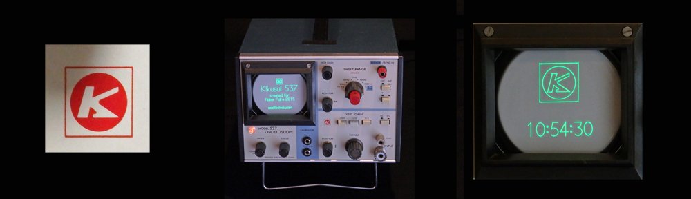
At last, we present the final model from that Faire – the Kikusui 537 Oscilloclock!
The Kikusui 537 was hand-picked for conversion by the lab’s youngest technician (9 at the time). He chose it for its small size and portability, but also for its cute colour scheme! A dainty red sweep adjustment knob highlights a bright white and black control panel, with a blue case providing overall contrast and visual soothing.
The 537 Oscilloclock’s small size makes it the perfect clock for an office desk, bedside table, or mantle. And since this is a ‘maximum re-use’ conversion, the existing circuit is active and all the front panel controls are fully functional. Fiddle with the image’s size and position to your heart’s content! Switch from XY mode to normal sweep mode, to view raw Oscilloclock signals in real time, as the seconds tick by!
History
The Kikusui Electronics Corp. logo
The 537 was manufactured by Kikusui Electronics Corp., a major producer of test equipment in Japan since 1951. It was produced in large numbers from 1975 and was extremely popular for its small form factor, solid-state design, 5 MHz bandwidth, and ‘low’ price of 45,000 yen (perhaps USD 1,000 in today’s terms). See the catalogue page (Japanese only) and the operating manual (Japanese and English).
Construction highlights
In a previous post, I mentioned there are several general approaches to converting an oscilloscope. Since the Kikusui 537 is fully solid-state (it uses transistors instead of valves/tubes, except for the CRT) and it is only 40 years old, I decided on the maximum re-use, minimal invasion approach. (I really should trademark that term!)
This approach involves tying the Oscilloclock Control Board‘s outputs directly into the existing X and Y amplifier circuits. This was easy to do in the 537!
Oscilloclock Control Board mounted in the 537
However, as discussed in the Circle Graphics post, we also need to be able to blank the beam at extremely precise intervals. Sadly, the 537 (like nearly all oscilloscopes of this vintage) does NOT have a convenient DC pulse-tolerant Z-axis input. I therefore installed an Oscilloclock Power Board, partially populated to serve as an isolated blanking amplifier, in series with the grid.
Partially populated Oscilloclock Power Board
Finally, an Oscilloclock Supply Board was needed to power the other boards.
An Oscilloclock Supply Board is also nestled in there!
Mounting the Control
What better place to fit the rotary encoder, than on the beautiful red sweep frequency adjustment knob that my junior technician liked so much! Here’s the general story:
Sweep adjust control in its original stateAfter removing the potentiometerThe encoder, after hacking with a hacksaw!Voila – sweep knob now drives the rotary encoder!
Like what you see?
One of the two Kikusui 537 Oscilloclocks crafted for the Maker Faire is still available for the special person with a soft spot for a krazy kikusui klock. Visit the Availability page for more information, and of course see the Gallery for other unique creations!


