They say that cats have ‘nine lives’. Oscilloclocks must, too. Read on…
Destroyed during delivery…
~Brian~ received his Kikusui MC-120 Oscilloclock in this horrid state:


But brace yourselves.
The worst scene is yet to come.
I still get nightmares…
Click here to expand – if you dare!

What happened?
On the surface, it may look like a massive explosion has ripped through the unit, leaving a wake of destruction. In fact, it’s quite literally the opposite.
As we’ve learned before, cathode-ray tubes (CRTs) operate in a very high vacuum to allow electrons to flow freely from the cathode to the screen. With such a low pressure inside but a high atmospheric pressure outside, damage to the glass results in an implosion. The CRT caves in on itself with phenomenal power, with a subsequent exodus of the shell and inner organs at a catastrophic speed. In other words? The implosion causes an explosion.
Take a look at this fantastic video from Tektronix in 1967, illustrating various CRTs being destroyed while observing at normal speed and in slow motion:


In the case of ~Brian’s~ MC-120, we believe the carnage began with the CRT implosion. Glass shards and metallic electrodes were ejected at high velocity. These projectiles smashed two precious tubes and snapped two of the four bakelite rods connecting the front knobs to the rear controls.


“Hang on! I’ve seen old oscilloscopes with broken CRTs before, and the rest of the scope wasn’t damaged like this. What gives?”
Well, in a normal oscilloscope or other display device, the CRT is protected from electromagnetic fields by a µ-metal shield. In the case of an implosion, this shield limits the ejection of projectiles, protecting the rest of the unit.
“What about the electronics under the chassis? Was there any damage?”
Yes. And this was NOT caused by the CRT implosion! Some of the boards had come loose, and the aluminium rails that were installed to guide the chassis to slide out evenly were almost inexplicably bent and battered…

HOW could this have happened?
It’s easy to blame the shippers and delivery crew. After all, the box must have passed through the hands of possibly tens of people, who would not all have the same respect for sensitive and delicate electronics that we do.
NO.
They did their jobs. They delivered the product.
The fault is at the source, and that’s where accountability remains.
The real reasons?
Here at Oscilloclock, we usually try to do everything we can to protect the CRTs and other components. Just take a look at our shipping precautions.
But hindsight is a powerful thing. We had taken a few too many shortcuts:
- The CRT clamp mechanism at the rear was too weak.
- We didn’t double-box, even though this unit was relatively heavy (11kg).
- The rear of the chassis was not screwed down during shipping.
Reviewing the damange, the most likely sequence of events is this.
- The box was oriented on its side or even upside down and subjected to substantial vibration or impact.
- The chassis bobbed around at the rear, jumping off its rails, hitting the top and bottom of the cabinet repeatedly, and shifting side to side.
- This movement damaged the rails, jarred the circuit boards loose from their support posts under the chassis, and smashed the Wave board at rear against the edge of the cabinet.
- With all the chassis vibration, the CRT neck slipped out of its clamp, allowing the neck of the CRT to smash hard against the hole in the vertical metal plate. While the hole did have a plastic bushing, the plastic was insufficient to cushion this impact.
- The CRT imploded, resulting in damage to the rods and the tubes.
In short, the structural design and packaging was inadequate for shipping.
Recovery… Or not?
You may well think, “the shipment was fully insured! Just claim some of the insurance, get the unit back, and repair it using those funds!” But unfortunately, that is not how shipping indemnity claims work:
International post offices (including Japan Post and USPS in this case) hold salvage rights. When the post office pays out the item’s insured value for damage or loss, they legally assume full ownership of the item and its packaging. This prevents “double recovery” (keeping both the cash payout and the item itself). It also helps the post office offset their insurance losses by auctioning off the damaged item.
So we had two options: Hand over the damaged clock to the post office and provide ~Brian~ with a full refund; or claim nothing, send the damaged clock back, and repair it at own expense.
Well, there may not be another Kikusui MC-120 oscilloscope left anywhere on the planet. And while the physical damage looked severe, everything was reparable. The Oscilloclock components under the chassis would be in good shape. And we do have spare SE4DP31 CRTs.
So, we chose the Return and Repair route. Hang the expense.
Kikusui re-Krafting
Several months later, it is with great delight and pleasure that we are able to present ~Brian~ with a fully re-crafted Kikusui MC-120 Oscilloclock!

On the surface, you may not see much difference to the original.
But it’s been built to survive harsh shipping and with longevity in mind — more than ever before!
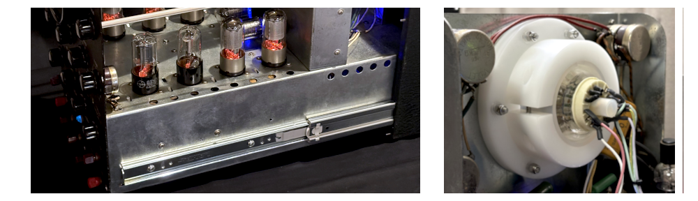
Suspended chassis
The chassis is now mounted directly into quality slide rails, similar to those used in desk drawers. These rails, proudly made in Japan, incorporate ball bearings floating amongst soft plastic runners, allowing for a degree of ‘give’ while still keeping the chassis firmly positioned. No more bobbing around.
For ~Brian~, there is a distinct improvement. The chassis can now be pulled out and returned more smoothly, with only the slightest touch!

Re-designed CRT clamp
We’re not ashamed to say that this new CRT clamp is a little over-engineered!

We machined this split clamp from a solid block of white acetal resin (a.k.a. POM). The bottom half of the clamp is bolted to the flange. The top half screws down into threaded inserts, with a thick silicon sheet providing some cushioning against the glass neck of the CRT. We used Loctite on the screws to ensure they wouldn’t come loose during shipping.

Custom designed!
Precision machined!

The flange is bolted to the vertical plate via a system of grommets, silicone washers, and silicone sleeves. This allows the entire assembly to ‘float’, giving the CRT some flexiblity to shift in any direction. The bolts are capped with locknuts to ensure that they cannot come loose.

Reinforced front panel
Previously, the front panel was affixed to the chassis only at the bottom, allowing it to flex especially when the chassis was pulled out from the cabinet. This might result in undue stress on the CRT, which is snuggled inside a gasket in the front panel.
We’ve remediated this risk by installing brackets at the top, effectively making the panel an integrated part of the chassis assembly.

Oscilloclock board mounting
The Oscilloclock boards were originally mounted using fasteners made from polycarbonate (PC) plastic. While none of these broke from the forces applied when the chassis jiggled around, careful testing revealed that unless PC nuts are significantly reinforced by doubling up or using locknuts, they can become loose – especially under the force of gravity when suspended upside down.
This is due to the very low friction coefficient of polycarbonate plastic.
During this re-craft, we instead chose screws, washers and nuts made from a polyamide resin. Besides having a far lower friction coefficient than PC, the screws have more than 3 times the torque and tension strength than PC, making them far more unlikely to snap under force.


Materials used
The CRT clamp was made from acetal resin (POM, sometimes known as Delrin). This is quite dense and has a satisfactorily high melting point.
All rubber cushioning components — grommets, tubing, sheets and washers — are made from either quality EPDM or silicone, with the exception of the CRT gasket at front which is made from chloroprene rubber (a.k.a. neoprene) sponge.
Metal fasteners such as screws, bolts, washers, nuts and threaded inserts are forged either from stainless steel or from Reny (a high-performance polyamide resin).
All materials were sourced from reputable local suppliers. These parts should last decades!
Shipping and packing
Like the proverbial cat, our MC-120 was now on its third life. We could not allow any further mistakes!
First, we protected the innards of the Oscilloclock from damage by applying layers of bubble wrap and air cushion material. We then wrapped the clock cabinet and snuggled it into expanded polyethylene (EPE) foam rails.
The outer box was custom-made from double-walled cardboard. We prepared this box with EPE foam sheets and rails, and lined the bottom with a layer of polystyrene peas. After inserting the inner box, we filled all gaps with peas and placed EPE foam on top.


And voila!

The Kikusui MC-120 Oscilloclock has now left the lab, and ~Brian~ awaits its safe arrival. We do hope lightning doesn’t strike twice! But if we have to do this yet again, we can. And we would.
Did you enjoy this tale of Kikusui karnage, Kikusui re-krafting?
Your humble Oscilloclock engineers are craftspeople based in Japan, following a local work ethic. We admit mistakes, we rectify them, and we learn from them. We never, ever, give up getting the job done, to make sure people are happy with our works of art. It’s what we do. It’s our legacy.