It’s a sobering thought, and not a particularly pleasant one, that your Oscilloclock might just outlive you…
But let’s not dwell on such talk! The real focus today is the oft-asked question: “How long will my Oscilloclock last?”
The honest answer is: we don’t know.
However, we do know how we try to maximize longevity, and we do have repair and return statistics from 15 years of delivering beautiful Oscilloclocks. We’ll go through all of this with you!
Your Oscilloclock
There are many different models and styles of Oscilloclocks (see the Gallery), with infinite variations in terms of parts that make up the final product.
But in terms of longevity, we can broadly categorize components like this:
- CRT – the cathode-ray tube display
- Hardware – the case, mounting supports, thermal parts, nuts and bolts
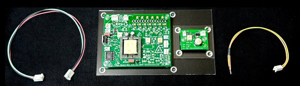
- Oscilloclock boards – the electronics designed and built right here in the Oscilloclock lab
- Original device circuitry – the host device’s original electronics that are kept in use (if any)
- Harnesses and cabling – wires, plugs and sockets; both internal and external
In today’s post, we’ll tackle the proverbial elephant in the room – the CRT!
Your CRT
Your clock’s cathode-ray tube is actually a type of vacuum tube. There is a glass enclosure, with a screen coated with chemical phosphor. It has a heater (or filament), and other electrodes made of special materials. These are welded to wires that are soldered to pins protruding through airtight seals in the glass.
Each italicized word adds up to this: A CRT is quite fragile!

CRTs have many “failure modes” – and we’ve seen them all! Let’s explore.
Failure mode A: Natural causes
Vacuum tubes (or valves) rely on thermionic emission. Electrons are emitted from one of the electrodes called the cathode, when it is heated up and voltage is applied.

In any vacuum tube, this emission capability decreases over long periods of active use. This is most commonly due to a degradation of the special emissive material and coatings that are used in the cathode.
Your Oscilloclock’s beautiful CRT will face the same issue eventually. As the number of electrons bombarding the phosphor screen decreases, the image will gradually get dimmer and dimmer, until eventually it cannot be seen.
How long will a new, unused CRT last before it succumbs? Well, manufacturers quote working lifespans of tens of thousands of hours of active use (heated and voltage applied). This equates to a few years.
We want our Oscilloclock CRTs to last decades, not years! So what do we do?
Secret 1: Auto Power Off

Strongly recommended by Oscilloclock labs, this feature simply turns the Oscilloclock off after a period of non-activity (not touching the control). Alternatively, owners can set a specific “Off at:” time.
It may sound counter-intuitive, but in practice, all Oscilloclock owners to date have been comfortable to turn their unit on just when they intend to enjoy it, and allow it to switch itself off.
For clocks that are permanent fixtures in offices and restaurants, staff manually turn their clocks on together with other appliances in the premises, and set them to turn off at the business closing time.
Secret 2: CRT type and manufacturer selection
While working with the owner to choose their CRT, we emphatically avoid tubes where the manufacturer quotes short lifetime ratings.
Sadly, some CRTs that are most readily available today fall into this category. See the data sheet below, specifying an incredibly short maximum longevity of just thousands of hours!

Q. What can be done for a CRT ‘on its last legs’?
Sadly, it isn’t feasible to restore a dead CRT to factory condition. But there are two things that can be done before it reaches that state, to prolong the inevitable:

Firstly, Oscilloclock owners can adjust the Intensity control, as described in the Operation Guide. This will drive the CRT harder and brighten the image.
Secondly, here in the Oscilloclock lab, we can attempt a CRT rejuvenation. This procedure involves carefully applying higher-than-normal voltages to the heater, and between certain electrodes. Done correctly, this can ‘peel back’ a thin layer of the cathode surface that has degraded or suffered from ‘cathode poisoning’, to reveal a more emissive layer of material beneath.
Q. Will a new (unused) CRT last longer than a used one?
Theoretically, yes.
BUT in all our experience at Oscilloclock.com, we see no evidence that new-old-stock CRTs last any longer than used ones.
Why is that? Well, most CRTs we use are harvested from laboratory test equipment. Most operators typically switch lab equipment on only when needed – so the accumulated operating time is often very short.
In fact, we openly encourage the owners to choose a pre-loved tube! We vet all our CRTs, testing them electrically and inspecting for any damage to heater, phosphor, glassware, or seals. No electrode is unturned; no emission-impacting detail is omitted!
Failure mode B: Humpty Dumpty
Humpty Dumpty sat on a wall…
Humpty Dumpty had a great fall…

If the CRT glass is cracked or broken, there will be rapid loss of vacuum inside, halting all electron emission. If voltage is applied, the heater will quickly burn out, due to oxidation.
All the king’s horses and all the king’s men,
Couldn’t put Humpty together again.
Sadly, several CRTs have arrived at our lab in this woeful state.
Secret 3: Shipping precautions
We take great pains to ensure that Oscilloclock owners do not experience a Humpty Dumpty episode.
- CRT mounting – in all Oscilloclock models we ensure the CRT is mounted with sufficient cushioning (silicon or rubber) against its mechanical supports.
- Double-boxing – all separable components of an Oscilloclock are individually boxed prior to packing into a larger box for shipping.
- Packing material – we use a combination of bubble wrap, foam peas, and Styrofoam to cushion the internal boxes and their contents.
- Box selection – we love to recycle, and we have loads of used boxes on hand. We pick the stronger ones and make sure they are the right size – large enough to fit cushioning material, but never so large that the inner boxes might slide around!
- Carrier – we have had extremely good results with the standard EMS service available from Japan Post, and this is what we always recommend.
- Insurance – we always insure the shipment to a sufficient value.
Thanks to this secret, to date we have only had one case of breakage for an item shipped out from our lab! And even then, the insurance claims process working with Japan Post was quite straightforward – if not even pleasant.
Failure mode C: Gassy CRT
No, CRTs can’t eat too many potatoes! But CRTs definitely do not like air.
A CRT may become “gassy” if too much air leaks in via the pin seals or a fracture in the glass, such that its internal self-healing mechanism (formed by the getter electrode) is overwhelmed.


On a gassy CRT, the image will become dimmer and dimmer until it disappears entirely.
While there is no true remedy for this malaise, an owner can postpone the inevitable by adjusting the Intensity control. And in rare cases, the CRT rejuvenation procedure described earlier may stimulate the getter electrode to mop up some of the excess gas.
Secret 4: Avoid potatoes mechanical shock
Gassy CRTs crop up occasionally, usually as a result of excessive mechanical stress or shock.
Besides shipping precautions (Secret 4), we are even careful when storing CRTs. Being situated in the Japanese archipelago, the Oscilloclock lab and all its contents must endure significant earthquakes occasionally.
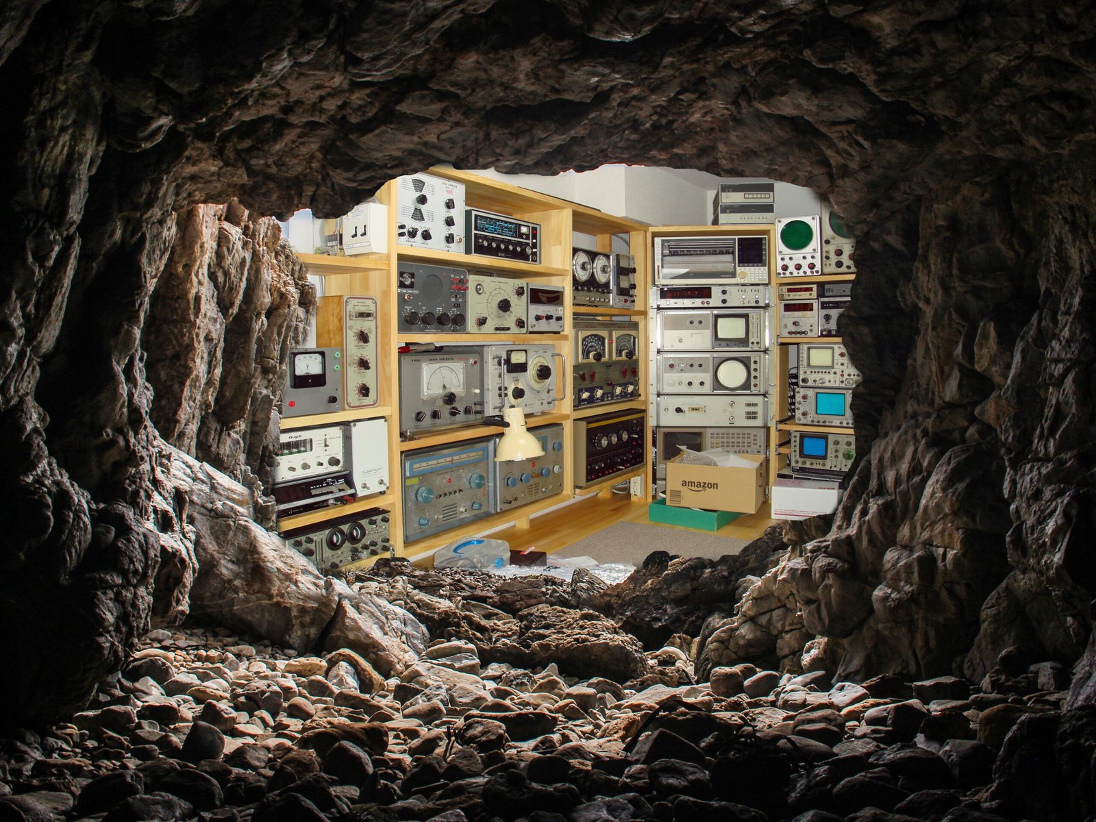
We therefore place the most precious CRTs in strongholds – small cavities in the woodwork that suffer less shaking and are very unlikely to collapse (even if the rest of the lab does). Touch wood!


Failure mode D: Phosphor burn
Roughly 10% of the CRTs we harvest exhibit a permanent scar, prominently visible to the naked eye…

To understand why this occurs, first think of an iron burn. If you deliver too much heat for too long into the same spot, your nice new Oscilloclock brand T-shirt will feature a prominent (and permanent) mark as shown below.

In a CRT, a beam of fast-moving electrons bombards the phosphor coating on the screen to produce an image. If the beam is too intense, or it is allowed to trace the same route on the screen over a long period of time, the phosphor compound may degrade and lose its luminance. The result:
- The screen won’t light up well in those spots any longer.
- The damaged areas may appear dark even with the power off – a ‘ghost image’.
Devastatingly, it just isn’t possible to restore the phosphor. But since these CRTs are otherwise perfectly healthy, we put them to good use in the lab for testing and experiments.
Secret 5: Choose a decent CRT
Some CRT types and brands are more susceptible to screen burn-in than others. Some factors include:
- The factory list price (you do get what you pay for)
- The manufacturer’s credit rating for reliability
- The phosphor compound used
- The thickness of the phosphor coating
- Any additional technology; e.g. aluminized screens
For more details, see our deep-dive post: Burn-in? Nope!
Secret 6: Screen-savers and other protection mechanisms

Remember the phrase “screen saver”? In the pre-LCD monitor days, most computers employed some form of software that would stop the same image being displayed for too long, to avoid screen burn-in.
In addition to Secret 1 (Auto power off), Oscilloclocks have several more screen-saving features that protect the phosphor:
- Hourly XY Bump – shifts the image by a small amount in the X and Y directions every hour
- Auto screen switch – cycles through the screens (clock faces) at regular intervals
- Bright/dim control – switches between preset beam intensities via a front-panel control (on some models)
- Intensity control – manually adjust beam intensity if required to suit darker rooms
For more details, see our deep-dive post: Burn-in? Nope!
Failure mode E: Disconnected electrode
Very rarely, the weld between an electrode and its connecting wire fails. Or the soldered joint between the wire and the external pin fails.
The symptoms depend on which electrode has been disconnected, but one thing is for sure: the CRT becomes defunct. How awfully sad.


Secret 7: Cry and move on…
I would like to simply write, “Choose a reliable manufacturer.” However, they don’t get much more reliable than Tektronix!
Besides protecting the CRT from mechanical shock (see previous Secrets), all we can do is accept fate…
Failure mode F: Open heater

Remember incandescent light bulbs of yore, with a delicate filament wire suspended inside the glass? They burned out over time – typically with a break in the wire that you could even see with the naked eye!
Well, the heater in a CRT is also formed from filament wire (albeit with different metals designed to emit more heat than light). If a CRT heater burns out, the cathode cannot be heated sufficiently to emit electrons, and the tube is rendered useless. A sad, sad state of affairs…
But what causes such failure?
Well, when did light bulbs typically fail? Yes! Right when you switched them on!
The reason is that a cold filament has a very low resistance. When you apply voltage, a huge amount of current flows (called inrush current). This settles as the heater warms, but the initial power and sudden temperature change causes metal fatigue. And after many switch-on cycles, the wire can break.
Secret 8: Soft-start!
The best way to preserve the heater is to limit the inrush current, so that the filament can warm up gradually. Every Oscilloclock employs one of the following 3 types of inrush current limiter:
1. The sacrificial lamb – a light bulb!
In this scheme, we simply place a specially-selected incandescent light bulb in series with the CRT heater. Upon switch-on, most of the supply voltage is applied to the light bulb’s filament (because the CRT heater’s resistance is low), making it light up brightly.
As the CRT heater gradually warms up, its resistance increases. The voltage across the light bulb decreases, making it dim and cool down, and its resistance lowers. By this time, the CRT has fully warmed up and stabilized, with most of the voltage now shifted to the CRT heater.
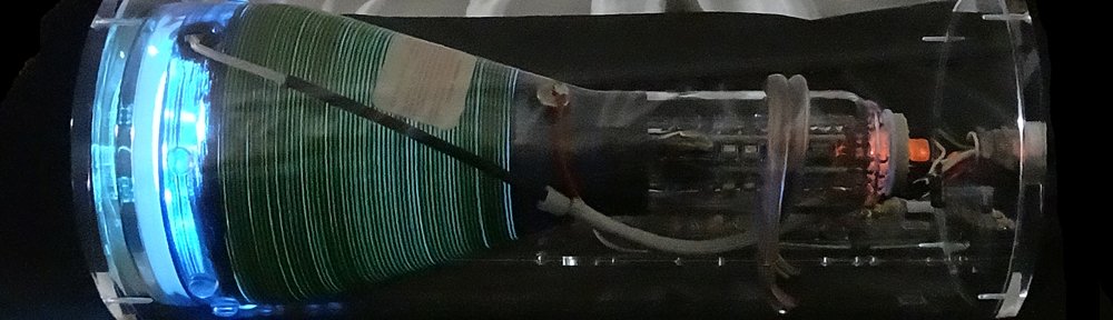
Functional, AND beautiful to watch! Besides the Exo in the video, we’ve used it in the Heathkit OR-1 Oscilloclock and a few other custom pieces.
2. Mister thermistor

These long-legged beauties are called thermistors. They have an odd characteristic called NTC (negative-temperature-coefficient). The hotter they get, the less their resistance!
Does that sound familiar? Yes! They can replace the light bulb used in method (1) above. Most of our Oscilloclocks employ these devices, because they are reliable, predictable, and very small.
Nonetheless, we enjoy the switch-on supernova of the old-fashioned light bulb. And some owners do, too!
3. Electronic soft start
Both light bulbs and thermistors are passive devices; their resistance vs. temperature profile is known (and can be charted in a specifications sheet). BUT they are not aware. They don’t have any kind of feedback loop, so they don’t actively control the voltage across the CRT.

Recent Oscilloclock Power Board designs provide an active soft-start option. This is a circuit that dynamically ramps the output voltage up from 0V to the final voltage in a preconfigured number of seconds.
Effective and reliable, but just a little more complex!
Q. Will running the heater at a lower voltage prolong the CRT?
No. According to many folks, running filaments at lower voltages than specified can accelerate “cathode poisoning” – degradation of the cathode material due to absorption or chemical reaction with trace foreign substances. We don’t recommend this.
Q. “Sacrificial lamb” approach – won’t the light bulb itself die?
Yes, eventually. However, it will certainly outlast the CRT filament. Although the light bulb filament does suffer a high inrush current, even a cold CRT presents a small resistance into the circuit. The voltage across the bulb at turn-on is therefore less than its rated voltage, and this extends its life.
Q. Isn’t there something that can be done to restore a CRT heater?
Maybe. Some folks have managed to ‘fuse’ a broken heater together, by injecting a very high voltage (thousands of volts) across the gap. The resulting arc effectively welds the broken filament. We haven’t yet had the pleasure of trying this, but if we do we will certainly write it up for you!
Replacing the CRT
Fact: In 15 years of crafting Oscilloclocks, not a single unit has ever come back for CRT replacement!
That said, every CRT we shipped will reach its end of life. It’s just a matter of time.
But don’t despair! Oscilloclock carries spares for most common tubes, and we can supply and replace them. Some owners even choose to purchase spare CRTs with their original order, so that they have them on hand.
Q. What about rare CRTs?
If a clock was crafted from a particularly rare CRT, there may be no spare available. But again – do not despair! We can work with the owner to select another type of CRT, and modify their precious device to suit. By rejuvenating their clock ‘with a twist’, the owner may experience even more of a thrill than if we simply restored it to its previous state!


Q. Can owners replace the CRT by themselves?
We always recommend shipping clocks back to the lab for CRT replacement.
However some models, especially those in the Oscilloclock Exo series, employ a simple and safe mechanism to swap CRTs – and we provide instructions in the Operation Guide for doing this.
Q. Does Oscilloclock.com produce or repair CRTs?
No. We dream of one day establishing a CRT factory. Or at least a CRT repair facility. However with all the toxic chemicals, high vacuum, glasswork, and intricate welding involved, this is likely to remain a dream.
Q. Are new CRTs being manufactured anywhere in the world?
Yes – some types of CRTs are being manufactured in some countries. However many are not suitable for Oscilloclocks. They may employ electromagnetic deflection (which we don’t yet support), they are special-purpose for military or aerospace applications (too expensive!), they are very cheaply-produced (not reliable), or they have short lifetimes per design and require frequent replacement.
Swappable CRTs!
Many of our ‘Full Package’ type clocks (see Gallery) support display swapping.
Essentially, we craft complete additional display units, which the owner can swap in at will simply by swapping cables to the Control Unit. There is no need to open a case, touch the CRT itself, or any form of delicate operation.


This is normally used to change the ‘mood’ of an Oscilloclock, by swapping in different phosphor colors. But it also can be used to more easily swap in a replacement CRT.
Do you want long life, both for yourself and for your precious electronic devices? Are you tired of modern society’s throwaway culture, built-in obsolescence, and device non-serviceability? Our goal: electronic artwork that might be passed down a generation (or more) in actual working order!
Stay tuned for Secrets Parte II, where we will explore the life of other components!


