Whether directly or indirectly, the pandemic seems to have slowed everything down: chip production; the global economy; and even Oscilloclock blog post publishing!
But perhaps most impacted of all is transport logistics. [Dante] in Brazil discovered this to his dismay in July 2020, when he purchased an Oscilloclock Bare unit. The P.O. had stopped all air service to Brazil just 3 weeks earlier – well after our discussions had started. Oh no!

[Dante] waited patiently for 6 months for the post office to resume accepting airmail service to Brazil. But they never did. And FedEx and DHL came at too hefty a price. In desperation, he authorized shipment by sea – and at last, in December 2020, his package was off!
Absence (of air mail service) makes the heart grow fonder...
After an agonizingly long wait, [Dante] finally received his unit 6 months later – in July 2021. He then spent the next 5 months completing his dream project!
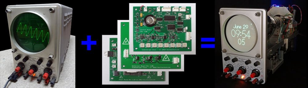
[Dante]’s Dream: A Hewlett Packard retrofit
The Oscilloclock Bare is designed to be a no-frills controller assembly that highly knowledgeable folks can install into their own displays. [Dante]’s dream was to use this to convert his beloved HP 182T / HP 8755C unit into a living, breathing scope clock.
And convert he did!


Clearly, [Dante]’s 18 month end-to-end was worth the wait.
The Build
[Dante] was kind enough to supply a write-up of his project, including some clever solutions for pitfalls along the way. Let’s hear from him in (mostly) his own words!
Motivation
The model HP 182T is an oscilloscope featuring a large CRT with a graticule of 8 x 10 major divisions and a display area of 133 cm2, coated with a P39 aluminized phosphor for high brightness and long persistence.
The HP 182T works as a display mainframe supporting other HP plug-in test equipment, such as the HP 8755C, a swept amplitude analyzer.
Both items are nowadays considered “vintage” test equipment. But with the Oscilloclock board installed, they have been transformed into a unique appliance with a natural appeal for practical use. Far better than the regular surplus market destinations, or — even worse — destructive disposal!


HP 8755C in short
This plug-in unit works primarily as a signal conditioner and a multiplexer for “almost dc levels” from three RF detector probes attached to three input independent channels. There are front panel adjustments for the scaling, gain and multiplexing controls that provide the appropriate Y-Axis composite signal for displaying by the HP 182T mainframe.
The Oscilloclock control board was elected to be installed inside this plug-in unit.
HP 182T in short
This oscilloscope is built around the CRT with its high voltage power supply.
The X-Axis signal from the Oscilloclock board is fed to the HP 182T’s chain of the horizontal pre-amp plus output amplifier, which drives the CRT horizontal deflection plates.
The internal wiring of the HP 182T connects the CRT’s vertical deflection plates directly to the plug-in cabinet of the display mainframe, so the Y-Axis signal from the Oscilloclock board is routed inside the HP 8755C itself.
The Z-Axis signal from the Oscilloclock board is fed to the HP 182T’s gate amplifier.


Drawbacks
Contrary to any standard X-Y scope where the two input channels are always supposed to have electrically similar (if not identical) characteristics, the correct operation of the Oscilloclock board for the application here was shown to be not as seamless as first imagined. You have to face some details of these integrated “host” equipment (HP 182T + HP 8755C) to see why…
As described, there are distinct amplification chains accepting the Oscilloclock output signals. This presents specific challenges regarding (a) the differential gain for the X and Y signals, and (b) the differential time delay between any combination of the three X, Y, and Z signal outputs of the Oscilloclock board.
First Approach
Before having the board at hand and expecting to make it work as soon it arrived (the shipping took longer than expected due to COVID restrictions), I first planned the signal flow and did the wiring. I had one eye on achieving a ‘clean packaging’ of the board inside the HP 8755C, and the other on ensuring compatibility between the Oscilloclock’s X-Y-Z output signals and their respective chains planned in the host equipment, considering signal amplitude and required frequency response.
The adaptations made at this time considered a minimally-invasive approach, where the criteria was to “make it simple”. This was limited to just opening or re-using connections and keeping the existing routing, in order to use the Oscilloclock’s X-Y-Z output signals in the most simplistic way possible.
Another necessary one-time adaptation was for the board’s power supply, and integration of its PSON output signal with the equipment’s hardware. This part of the design was successfully kept to the end of the project without any further modification.
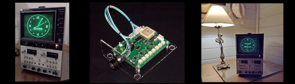
First time installation of the oscilloclock board
Upon arrival and a bench test of the Oscilloclock board with a scope, I immediately figured out that the amplitude levels for the X and Y output signals were lower than expected (maybe due to my misinterpretation of the specs). I did the gain compensation corrections again and went thru the complete installation of the board inside the host equipment, anxious to see it working.
What a disappointment when instead, up came a completely distorted and elliptically shaped image, blurred with noise, and what looked like un-blanked retrace lines. Worse yet, mainly when alphabetic characters were displayed on the screen, none of the shapes were correctly formed.
Of course, that was time for a break — and a complete review of the job and the work done so far!
Chasing the problems
The Lissajous figures generated by the Oscilloclock board use an approximately 40 KHz sinusoidal signal, so I started to play with an external generator at the same frequency and amplitude for the X and Y signals (at about 1 Vpp) and trace it inside the HP 8755C and HP 182T.
At this time, I’d already exercised the Z-axis waveform from the Oscilloclock board and the expected processing through the HP 182T. There was no evidence of problems with this Z-axis signal chain, and I achieved a measured propagation delay of around 50 nS.
The minimalist approach mentioned earlier showed its consequences, when a propagation delay of an impressive 8 uS was measured at the vertical deflection plates, and around 1.5 uS at the horizontal deflection plates! It was time again for another break, to elaborate a new routing scheme for the X and Y signals.
Final Approach
From the previous analysis, I ended up with two different and both very large propagation delays for each of the X and Y signals (as compared with the measured 50 nS for the Z-axis). How to solve this? It did not seem to be only a routing problem.
I decided to investigate X-Y-Z signal propagation delays in the two units separately. After a thorough measurement of propagation delays inside the HP 182T itself, comparing with the HP 8755C plug-in itself (where the Oscilloclock board was installed), I concluded on two countermeasures:
1. The complete removal of the Processor board XA-6 from the HP 8755C. (This is where the Y-axis signal from the Oscilloclock board had initially been connected.) Instead, this routing was transferred directly into the Normalizer Interface board XA-11 (which interfaces with the HP 182T).
2. Also at the Normalizer Interface board XA-11 inside the HP 8755C, the substitution of two original op amps U9A and U9B (HP #1826-0092) by TL072 op amps, which are faster and have a higher slew rate.
These solutions were enough to align the signal propagation and complete my project!
Dante JS Conti, 8 November 2021


Like what you see?
We do! We love to hear back from Oscilloclock owners, to hear their stories.
Check out our previous posts and the Gallery for info on other unique creations!