In Transformer Corner part 1, I introduced one of the key parts of the Oscilloclock – the HV transformer, and tried to illustrate some of the concepts and history behind it.
Next, let’s explore the Prototype’s power supply configuration. This will tell us a lot more about the transformer I had to wind!
Power supply design
My greedy little Oscilloclock wanted lots of different voltages…
By the time you read this post, you must have seen the term “Circle Graphics” in a thousand places across the site.
In fact, “Circle Graphics” is not an official term – I just use it to describe how shapes are drawn on these clocks:
Everything you see on this screen is made up of CIRCLES! Blank out part of a circle and you get an arc. Squish an arc and you get a line. This clock simply draws circles, lines, and arcs of different sizes at various points around the screen. It does it quickly. And it does it very, very well!
The effect of using circles is beautiful – shapes are smooth and precise, with no jagged edges or pixelation.
Making “perfect” circles
I carry on as if it were some incredible new concept or discovery, like the Higgs boson. But in fact, the analog technique of constructing perfect circles, ovals, and lines on a CRT is very, very old. These figures are really part of a class of shapes called Lissajous Figures.
Oscilloclock.com proudly presents a new feature – Seasonal Treats !
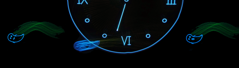
This month, the ghosts come out of the attic and merge with the electron stream, leaving their telltale prints in the phosphor… but if you get too scared? Just push the button and blow them up!
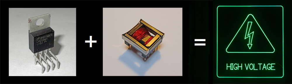
The atmosphere at Oscilloclock.com has been charged lately. Mails have been pouring in from folks who want to generate high voltage for their CRT projects, but have instead ended up with high tension from frustrated attempts. The primary culprit? Lack of a decent HV transformer.
HV Transformer basics
CRTs require high voltage, to coax electrons out of the electron gun and then accelerate them towards their fiery demise at the screen. This voltage can range from hundreds of volts for small tubes, to tens of kilovolts for large tubes! In the case of the Prototype and Model 1 CRTs, around 3kV was needed.
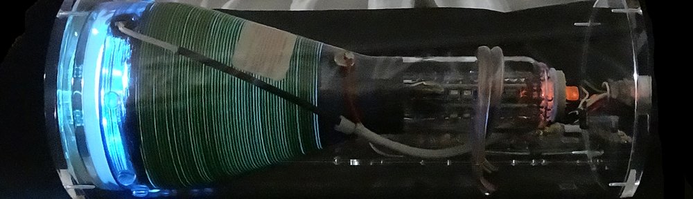
One of the most exciting things you can do with a Scope Clock is to simply look at it from behind! In many CRTs, the anode coating (a conductive black surface sprayed onto the inside of the glass) doesn’t extend all the way to the screen – leaving a nice gap of clear glass from which to observe the beautiful electron beam.
Ha – you can put down your magnifying glasses now.