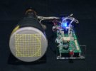
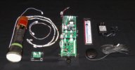
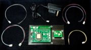
Here at the Oscilloclock lab there’s nothing more pleasurable than helping put a cherished vintage oscilloscope back into action. A new lease on life!
That’s why when [Chris] reached out about his early 1970’s Conar 255 oscilloscope, wanting to convert it into a Vectrex gaming machine, we were naturally excited!


The original Vectrex was an incredibly cool device. Instead of the pixelated, blocky graphics of the time (anyone remember Pac-Man?), the system used vector graphics to draw smooth line-art images. Each vector was a straight line, or a smooth arc, connecting point A to B. Vectrex games were true works of art, and the original hardware is quite rare (and $$$)!
Scopetrex

Well, [Chris] caught the vector graphics bug. But he decided to build a Scopetrex – a hardware emulator that allows you to run Vectrex games on an oscilloscope! He would theoretically just connect this to the Conar 255’s existing X, Y, and Z (blanking) inputs.
We like this “minimum invasion, maximum re-use” approach. We’ve gone down this route numerous times to craft Oscilloclocks out of still-usable hardware. (The alternative? Install a full set of modern boards that drive the CRT directly.)


[Chris] got down to planning. He could interface the X and Y inputs easily. But he faced a problem with the Z (blanking, or intensity modulation) signal, which instructs the scope when to turn the beam on and off:
- The Scopetrex outputs a 5V DC digital blanking pulse.
- The Conar requires at least 20V peak-to-peak blanking signal – and employs analog AC coupling.
We’ve solved this mismatch problem before using various non-standard Oscilloclock board setups and complex hook-ins to the existing circuits. Always on a case-by-case basis, always unique.
But now, at last, it was time to standardise the process. To make it easy. To adapt any vintage oscilloscope for digital blanking from a microcontroller! We proudly announce the next member of the Core family: The Z Core!

How to install it
Believe it or not, the minimal installation requires just 3 steps. For almost any oscilloscope! The Z Core effectively sits in series between your device’s blanking supply and the CRT grid.

- Snip the wire connecting to CRT grid.
- Connect the orange wire from the Z Core to the circuit side of the cut wire.
- Connect the green/yellow wire to the CRT grid.


Visit the Z Core Support Page for lots more detail, including the obligatory warnings about high voltage. There are also details on how to connect the Z Core to your controller, detailed specifications, and some fun Q&A to help answer your most burning questions!
The Z Core 2 Ex!
We’ve wanted to develop a dedicated, built-for-purpose Z Core product for a very long time. This would consist of a single, miniaturised, low-power board called (ingeniously) a “Z Core Board”, and a few harnesses.
But [Chris] didn’t want to wait for Oscilloclock labs to work through its ever-growing bucket list. Could we deliver within 2024?
Yes!
In past retrofits such as the Kikusui 537, we’ve taken spare boards that were originally designed for fully-featured Oscilloclocks, and partially populated them with only the necessary components to serve the blanking purpose.

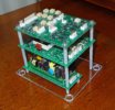
For [Chris], we found an almost fully-populated new-old-stock Power Board v2.27 and compatible CRT Board v1.21 lying around, just dying to be used and loved by someone. Older revision boards do tend to be set aside, as folks want the latest and greatest.
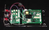
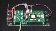
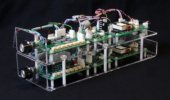
With just a few minor modifications, this assembly shipped – and is now branded as the Z Core 2 Ex. The “2” refers to the Power Board’s major revision, and the “Ex” stands for “external blanking amplifier” (the function of the CRT Board). The Power Board rev2.2x series boasts an on-board blanking amplifier, but this section wasn’t already populated. What a great opportunity to use up a stock CRT Board!
[Chris] will be happy. And we’ll keep up this spirit of minimising waste. You’ll see some other Z Core assemblies popping up in future: a Z Core 1 Ex, a Z Core 2, and potential variations of Z Core 3’s.
And finally, one day, a genuine dedicated Z Core will be born!
Why your scope needs a Z Core …
Many old oscilloscopes simply don’t have any input for Z blanking, Z axis, intensity modulation, or cathode modulation. (Look carefully – it goes by many names!) Or, the input may be there, but it’s not compatible with a microcontroller. Why couldn’t the designers offer a decent interface?
Well, it all has to do with high voltage! To get there, let’s cover how CRTs work in just three short sections:
Gun
A cathode-ray tube (CRT) has an electron gun that shoots electrons at the phosphor molecules on the screen. The electron beam is deflected by putting positive and negative voltages into electrodes placed in the CRT’s neck, and this is how patterns are drawn on the screen.

But the electron beam has to be turned on and off, to break the pattern and make meaningful images on screen. This is known as blanking.
Blanking
Oscilloscopes, particularly, have to blank the beam when it goes back (retrace), from the right to the left again. If there were no blanking, you’d see a retrace line – wickedly cool for us artists, but devastatingly distracting for engineers who want to focus on the waveform itself!


Oscilloclocks also rely on blanking. In Circle Graphics, where all figures are composed of lines and circles, blanking is crucial to creating meaningful segments. For example, a “C” is readily created from an ellipse “O”, simply by blanking the beam at just the right place!

Grid
CRTs are designed for blanking. There’s a valve-like electrode called a grid that sits inside the gun, just in front of the cathode where the electrons are spat out. If you inject a negative voltage into the grid (compared to the cathode), it repels those electron babies and sends them back where they came from. They don’t bombard the screen, and no more light is emitted. Blanking in action!

A fuller explanation – from The Bible

A change in grid voltage influences the field distribution of the first lens, and in so doing controls the emission from the cathode. For any fixed value of voltage applied to anode 1, it influences the number of electrons which pass through the cross-over point. Let us see how this comes about. In Fig. 5-17 is shown the field distribution in the first lens for two values of grid bias, O and -30 volts, and a fixed value of voltage on the plate.? It is clearly evident that with zero bias, the area adjacent to the cathode, between the cathode and the control-grid aperture, has a comparatively high positive potential as the consequence of the field between the control grid and the first anode. Under such conditions of zero grid voltage, it has been found that the area of the cathode which is emitting corresponds approximately to a projection of the area of the grid aperture; the maximum number of electrons are passing through the grid opening and the beam-current density is high.
When the control grid is made negative by an increase in the bias, —30 volts in the illustration, the field distribution in the vicinity of the cathode is altered so that only the center of the emitting surface is behaving as an emitter. The other areas are influenced by the space charge and effectively are not emitting. The result is a reduction in beam density and several other related effects.
High voltage
So – back to the high voltage aspect. The cathode and grid are usually about 2kV (that’s right – 2,000 volts!) negative compared to the rest of the circuits. If you connected an external input signal directly to the grid, something would fry.
Old-school oscilloscope designers took a very easy (read: cheap) solution: they stuck a high voltage capacitor between the grid (or cathode) and the external signal. This is called AC coupling because the capacitor blocks the DC voltage (2kV), and only couples through the AC (the fluctuating blanking) component of the signal.


This method of intensity modulation was fine for the regular, repeating signals observed in old TVs and radios. But it isn’t what [Chris], or so many millions out there like him, needs! They need to send through an irregular, sometimes not-fluctuating-at-all (i.e., DC) signal. They need DC coupling! And it has to be isolated – standing off more than 2kV!
And there’s another voltage related problem: the grid has to go substantially negative with respect to the cathode, in order to completely block the electron flow. We’re talking 20-50V typically. This is not a voltage that a modern microcontroller board will deliver! This requires an amplifier.
Summing it up
So that’s it! Just three(?) words. We need an isolated DC-coupled amplifier. And it needs 2kV isolation with a 10x amplification factor.
Welcome to the Z Core!
Demo
No assembly can leave our lab without being fully tested, and without a demonstration to ensure the customer’s utmost satisfaction. Here’s how the demo went:
The host device: Trio CS-1554

This venerable Trio (also branded as Kenwood) hails from around the same era as the Conar 255. It was attractive, had fairly good specifications, and a low(-ish) price tag, making it very popular both in Japan and overseas. Documentation is freely available and… more importantly, I had one lying around!


Of course this device is full of high voltage oil capacitors. These were effective in their day, but they break down over time, and things get very nasty. One particular HV capacitor in this unit was overheating to the point that the metal case had warped, and oil was even leaking out! Ick.
A few modern-day capacitors hacked together replaced the leaky unit and saved the day. Onwards!
The controller: Oscilloclock Connect

As mentioned on the Availability page, one lovely Oscilloclock Connect unit is in stock. What better controller to verify the Z Core’s performance?
The demo
- Connect Connect X output to Trio EXT HORIZ input at rear 1
- Connect Connect Y output to Trio CH1 vertical input
- Connect Connect Z output to Z Core input 2
- Connect Z Core outputs to Trio CRT grid and grid circuit (as shown in earlier section)
- Incompatibility! The Trio’s horizontal input seemed to want 10V peak-to-peak for maximum deflection (this is way off its original specs of 250mV/cm. I think it’s broken!) The Connect by default has only a 3V peak-to-peak output signal. The image is going to be small… ↩︎
- Trickery! The Connect by default is designed for a display device with a high-impedance Z input. The Z Core 2 Ex has a low-impedance input and 15mA drain at 5V. A temporary mod was needed in the Connect – which was promptly reversed after the test. ↩︎


The result? A relatively clean image, albeit small! But the blanking works well. [Chris] was okay with the jagged edges and other blemishes; these are attributable to the Trio’s rough condition.

Performance testing
The Oscilloclock cave is not a precision testing laboratory. But we do have a significant collection of equipment, and every piece plays its part. In this case, we deployed a Hewlett Packard 1901A Pulse Generator.

Choosing amongst a plethora of delightful old oscilloscopes, we stayed with the HP theme and used a venerable but still digital HP54615B.

The setup was simple:
- Set up the pulse generator for 100kHz square wave
- Set rise and fall times to minimum (around 10ns)
- Set output to 5V and connect to the Z Core’s input
- Connect a 20pF capacitor across the Z Core’s output, via the standard 200mm 22AWG harness
- Connect Ch1 of the scope to the input, Ch2 of the scope to the output

Results
| Measurement | Assembly: Z Core 2 Ex |
|---|---|
| Waveform base voltage | -46V |
| Rise time | 130 ±10 ns |
| Fall time | 180 ±10 ns |
| Propagation delay | 120 ±10 ns |
| Effective bandwidth | DC to 3 MHz (limited by rise/fall time) |


These results were satisfactory. But at some point, we’ll try the same with a Z Core 1 and a Z Core 3. And one day – a purpose-built pure Z Core. Stay tuned!
In conclusion
Well, that’s a wrap! The tested assembly has now shipped, and soon [Chris] will be able to try out a Scopetrex on his minimally-modified Conar oscilloscope. Fingers crossed!
For more technical info, fun facts and Q&A, check out the Z Core Support page. And for a peek at our range of gadgets, be sure to check out the Gallery.


