“Made in Japan” — a label so rarely seen on electronic equipment today.
But there was a time.
That time was 70 years ago.
That time is Now.

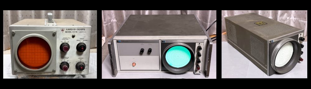
Presenting the Kikusui MC-120 Oscilloclock!
In 2025, ~Brian~ reached out to commission an Oscilloclock build. He had just 3 requirements:
- He wanted a custom conversion of an original vintage device.
- The device should have a large screen — at least 4″ diameter.
- The finished clock should include the Metropolis theme feature.

We prepared an exclusive catalogue with select devices in our stock that would meet the large-screen requirement.
~Brian~ immediately spotted the model he wanted!

It seems the finish of this unit reminded him of military devices his grandfather had once owned. Well, your senior Oscilloclock engineer certainly knows the influence a grandfather can have. A great choice, for all the right reasons!
Fast forward to May 2026 — and the labour of love was complete!

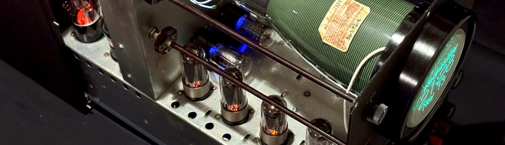
Oh, my! Just look at those internals!
We discovered at an early stage that the MC-120’s chassis slides out from the case relatively easily. Could we reduce friction enough that ~Brian~ could easily pull the unit open any time he wanted to gaze at the internals?
ABSOLUTELY we could, and we did!
But we took it one step further, by installing LED lighting into the tubes — simulating the look and feel of the original ‘scope in actual operation!


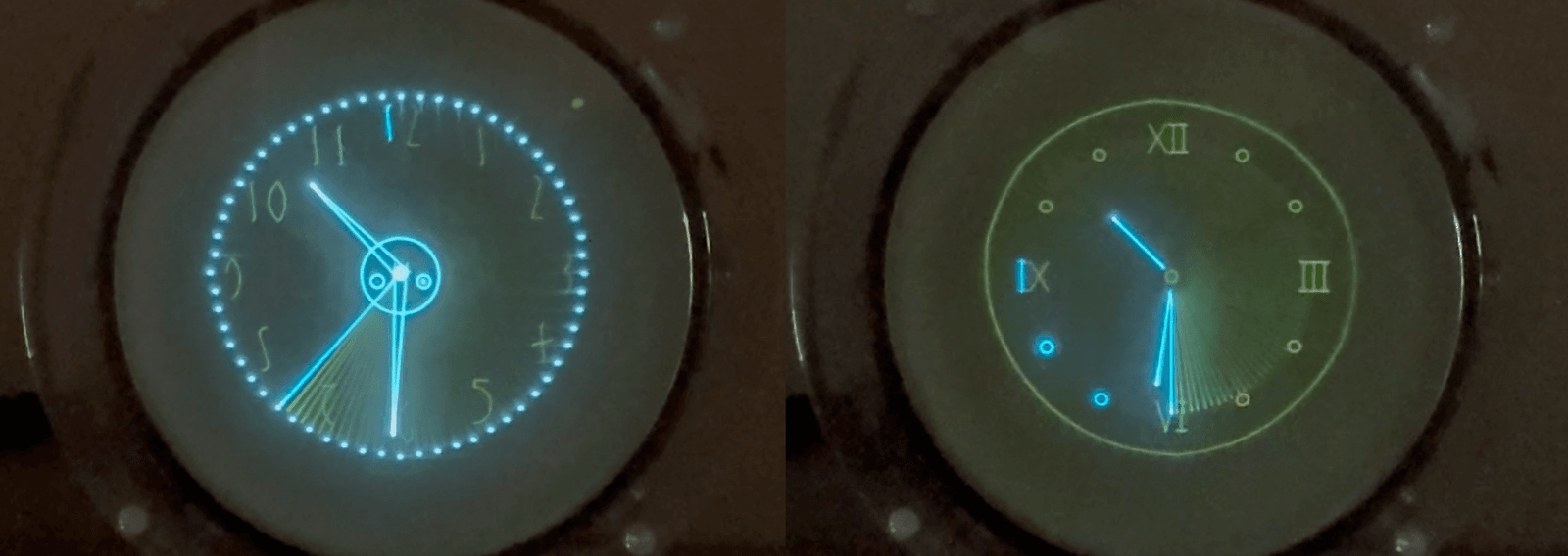
Metropolis marks its 100th anniversary
True to ~Brian’s~ every desire, his clock features the Metropolis themed screens, in addition to the the standard screens always available by default.
This is perfect timing(!), as 2026 marks the 100th anniversary of the marvelous Metropolis movie by Fritz Lang!

Latched on to Panels
Avid readers may remember that we LOVE oscilloscopes that have panels. Especially those with latches. Check out our posts here, here, and here! We can’t resist playing with them, and we are absolutely not alone in this fetish.
Well, this MC-120 also has a lovely latch panel in the rear. We’re not using it for anything. But look carefully! You can just see one of the LED-lit tubes inside…

Wave for the camera!
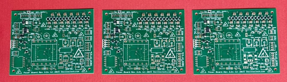
How do Oscilloclocks keep accurate time? We’ve written a full treatise before about the various options available. For the MC-120, we chose to install a custom Oscilloclock Wave board enabling NTP time synchronization over WiFi.
This board has been designed specifically to replace the no-longer-necessary fuse box in the rear of the scope:

Wait – reduce Weight!
The Kikusui MC-120 in its original form weighed at least 20kg (45 lbs). ~Brian~ accepted our pragmatic suggestion to strip out the original power transformer and choke coil, bringing the weight of the entire unit down significantly.
This weight loss helped greatly to reduce force required to pull out the chassis. But equally importantly, it halved the shipping costs!
During the build, we also stripped out a number of other components. But don’t worry, most will not go to waste. Tube amp enthusiasts love transformers!!

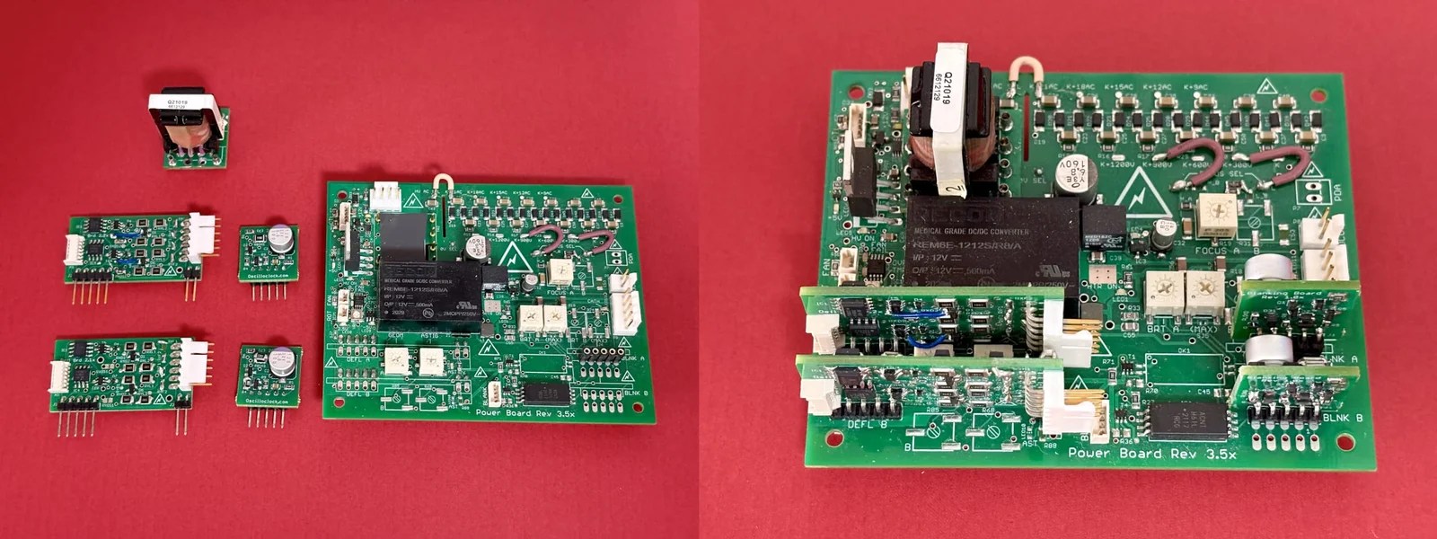
Hang on, where’s all the circuitry??
~Brian~ wished to retain the orginal looks above the chassis, so we mounted all Oscilloclock circuitry underneath!


Like what you see?
Actually, we hope you don’t like this specific Kikusui MC-120 too much, because it’s unlikely that we will ever come across another one! But never fear; we have other devices aplenty. We must have something special for you. And we can do some special things with it. Just let us know your ideas.