Connect !!

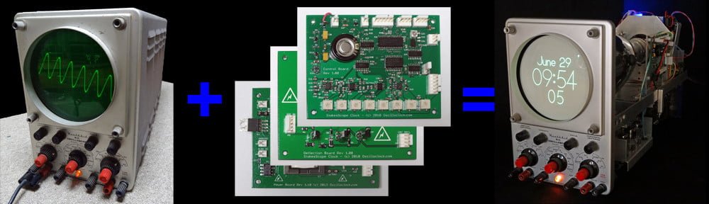
These days, just about everyone has an old oscilloscope lying around. You know, an old, dusty, derelict scope handed down from Grandpa (or Grandma). Well, [Paul] had something even better – an old Tektronix 602 X-Y Monitor! Could an Oscilloclock Control Board drive this vintage beauty? Absolutely. Could I make an aesthetically pleasing case? Definitely. How about time sync via WiFi? Stock standard!

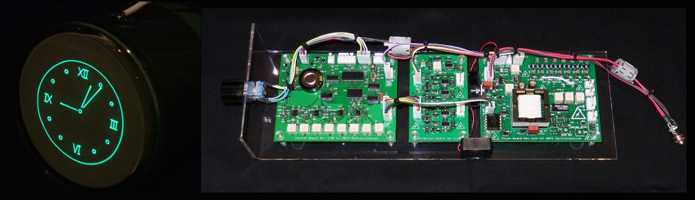
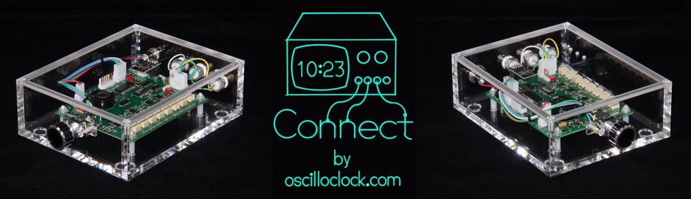
Presenting the Oscilloclock Connect:

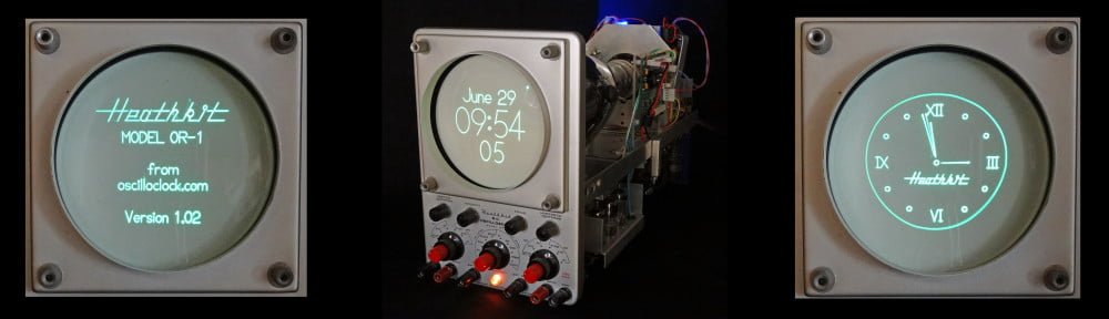
Here’s what it looks like plugged in to my fabulous old Tektronix 620 monitor:

And why not have a pair of Connects drive a Tek 601 and 602?

The Build

The main component of the Connect is, of course, a standard Oscilloclock Control Board. As usual, all 121 parts on Paul’s board were individually mounted and soldered by hand. The board then was programmed and underwent rigorous inspection and testing. Finally, the board was cleaned to remove flux and renegade flecks of solder, and sprayed with HV coating for humidity protection and – arguably more importantly – to give it its glorious sheen.

The case was custom-made and professionally machined right here in Japan from 6mm-thick sheets of pure cast acrylic (not extruded). This is an extremely transparent, hard, high grade acrylic – and Oscilloclocks deserve nothing less!

The case was sprayed with a special acrylic cleaner and static protection solution, before fitting the various components. Naturally, every part was cherry-picked, right down to the three BNC connectors – they needed an aesthetically pleasing colour, but they also had to have a shaft long enough to mount through 6mm-thick acrylic!

Finally, the physical interface! The knob was chosen for its perfect finger-fit and delicate aluminium/black tones, which gently contrast with the rest of the unit.

The Compatibility Crisis

Over the years, many folks have observed that the scope at hand has an “X-Y mode”, and asked if they could just ‘plug in’ an Oscilloclock Control Board. “Is it compatible?” Unfortunately, the response has usually been disappointing.

You see, creating figures and characters with Circle Graphics relies on the scope’s ability to turn the beam on and off at split-second intervals. This feature is called a “Z-axis input”. While many scopes from the 80’s and beyond do sport such an input, there are two common limitations:

Limitation 1: AC-coupled Z-axis inputs

Capacitive coupling – effective at isolating the input from cathode potential (-1260V !)

The input is connected to the CRT’s grid or cathode circuit via a capacitor. This is a low-cost, effective way to isolate the (usually) very high negative voltage of the grid circuit from the input.

The problem here is that the capacitor, by its very nature, removes the edges from the pulse. The controller is no longer able to control the beam on/off timing, and you end up with uneven blanking across the segments, as shown in the screenshot at right.

Depending on the values of the capacitor and the surrounding resistors, the symptoms may not be severe. However, the best way to resolve this problem (while still keeping the oscilloscope’s original circuit intact) is to insert an isolated DC blanking amplifier directly in series with the grid (or cathode). See the Kikusui 537 Oscilloclock for an example of this.

LIMITATION 2: INSUFFICIENT BLANKING AMPLIFICATION

Most oscilloscopes tend to require at least +5V on the Z-axis input to noticeably blank the beam. The Connect, however, is only capable of delivering +2.5V. It works just fine if you set the scope’s Intensity control very low, but as you increase intensity, the blanking quickly becomes ineffective.

Below we have a beautiful Japanese YEW (Yokogawa Electric Works) 3667 storage scope. The left shot is misleading due to the camera exposure; the displayed image is actually extremely dim. The right shot shows the same* image with the intensity control increased – the image is bright, but there is no blanking!

* Astute readers will observe that the time is significantly different between the two shots. This is a result of the WiFi NTP sync kicking in right in the middle! More (or less) astute readers may also notice that the scope’s trace rotation is not adjusted very well…

Of course, it would be a simple matter to incorporate a pre-amplifier for the Z-axis, which would solve this problem. This will be introduced with the next Control Board revision!


Like what you see?

Nothing brings more joy than connecting this bundle of usefulness into a woefully unused old oscilloscope or X-Y monitor. If this is of interest to you, visit the Availability page for more information, and of course see the Gallery for other unique creations!

The Oscilloclock Core

Over the years, folks out there have reached out to me with all sorts of crazy ideas about cases and housings for scope clocks and custom CRT displays. Here are some interesting examples:

  • The console of a vintage pipe organ
  • An ancient grandfather clock
  • A cylindrical case made of some exotic wood
  • A “cathedral” style vintage radio

Essentially, these people wanted just the innards of an Oscilloclock, which they would build into their own case. Could I help out?

Absolutely! For people who want to roll their own cases, and who have experience handling high voltage electronics and CRTs, I occasionally prepare custom board sets that are lovingly hand-assembled, tested, and tweaked for optimum performance with a given CRT. Here we go:

The Oscilloclock Core

Oscilloclock Core, hand-crafted in 2015 for a discerning customer in Germany

An Oscilloclock Core, hand-crafted in 2015 for a discerning customer in Germany


The standard Oscilloclock Core layout, on a test acrylic mounting

The standard Oscilloclock Core layout, on a test acrylic mounting

I supplied this particular unit with an 8SJ42J Chinese-made CRT, just for testing purposes. This is a 3″ PDA tube with a highly restrictive rectangular viewing area, but the customer found it just great for checking things out!

Oscilloclock Core - complete set for 8SJ42J - 03Oscilloclock Core - complete set for 8SJ42J - 06
Oscilloclock Core - complete set for 8SJ42J - 02

What comes with it?

Here’s what’s comprises the typical Oscilloclock Core:

  • 1 x Fully assembled and programmed Control Board (optional on-board GPS)
  • 1 x Fully assembled Deflection Board (latest ultra-linear revision)
  • 1 x Fully assembled Power Board optimised for a given CRT (latest revision with options: onboard high-bandwidth blanking amplifier, rotation coil supply, auto fan speed control, unblanking plate modulation, and isolated bright/dim input)
  • 1 x Fully assembled CRT Board (optional; an external blanking amplifier recommended when the CRT cable is longer than 50cm)
  • 1 x Rotary encoder
  • 1 x Worldwide 9V power supply (high quality wall wort unit, commercial ratings)
  • 1 x Garmin GPS unit with 5m cable; wired to board-side connector (not required for onboard GPS)
  • 1 x Set of standard inter-board and CRT harnesses for testing and reference (10kV/3kV silicone melt-proof used for HV cables, other LV cabling also heat-resistant)
  • 1 x Cast acrylic test mounting assembly, fitted with the boards, ready for testing out-of-the-box with your CRT
  • 1 x Ceramic adjustment screwdriver
  • Service documentation (schematics, board layouts, complete Digikey BOMs, harness specs)
  • All components are latest available types sourced within the last 6 months, 0.1% or 1% tolerance resistors, minimum 2 x rated working voltage capacitors, all lovingly hand-mounted by myself
  • All boards sprayed with HV lacquer for moisture and arcing protection
  • 2-week satisfaction guarantee. But no long-term warranty on board-only purchases

Naturally, the lengths of all harnesses and inter-board cabling can be customized according to the owner’s requirements. And there is also an Oscilloclock Core Cube arrangement, where the boards are stacked to reduce the length and width of the overall unit.

What CRTs does it support?

The Power Board and Deflection Board are increasingly flexible with each revision, but I insist on performing all configuration of the Core here in my lab. This allows me to tweak for maximum performance, and provide a proper satisfaction guarantee.

Typically I work with the owner to recommend a CRT based on preferences such as size, colour, and aesthetics. However in cases where the owner already has a CRT in mind, and I don’t have the particular CRT or a close equivalent, I ask the owner to send me one to test against. Or, I simply procure one; after all, one can never have too many CRTs!  (Though my better half does not agree…)

The current Oscilloclock Core board revisions meet the following operating parameters:

  • Maximum cathode to deflection voltage of 2175V
  • Maximum accelerator voltage of 3525V for PDA type CRTs
  • 6.3V heater, max 0.7A
  • Support for “Deflection Blanking” CRTs (see treatise here)
  • CRT rotation coil supply (+/-5V)
  • Precision deflection amplifier capable of driving +/- 275V with 0.1% linearity

Like what you see?

Check out the Availability page for more information, and of course see the Gallery for some unique CRT creations – many with an Oscilloclock Core at their heart!

Making the Heathkit Oscilloclock

Last month’s post about the Heathkit Oscilloclock generated tremendous interest, and I’ve heard from several folks keen to try their hand at preserving their own beloved instruments.

… so let’s take a brief look at what was involved in the Heathkit OR-1 conversion!

Heathkit Oscilloclock - inside

Approaches to conversion…

There are many approaches to retrofitting a scope into an Oscilloclock, but it really boils down to how much of the original circuit you want to re-use, vs. what you will bypass with Oscilloclock boards.

Continue reading

A Heathkit Oscilloclock!

Anyone familiar with Heathkit®?

From 1947 to 1992, the U.S. based Heath Company produced electronic kits for everything you can imagine: radios, TVs, computers, robots, ham gear, and electronic test equipment. Yes, you guessed it – they also produced kits for oscilloscopes!

My Grandpa purchased one such scope, the Heathkit OR-1, around 1960. He wanted to kick off a new career in electronics repair, and the ‘build-your-own-equipment’ approach to training was in full bloom at the time. Also, since this was before the era of cheap overseas manufacturing, he could buy a Heathkit far cheaper than an assembled scope.

Heathkit OR-1 manual - a work of art

Heathkit OR-1 manual – a work of art

Unfortunately, Grandpa’s electronics career never really took off. But decades later, he introduced me to his gorgeous oscilloscope, and boy – did that kick MY career off! Much later, the OR-1 came to live with me. (You can read a bit more about my affinity for this scope in my History page.)

The problem is, I have too many oscilloscopes. But I don’t have enough Oscilloclocks. What more fitting way to keep Grandpa’s legacy alive, than to retrofit his Heathkit?

Heathkit OR-1 Oscilloclock

Heathkit Oscilloclock - Splash and Clock

Special features

Continue reading