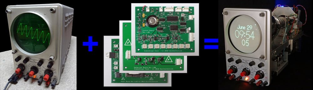
Last month’s post about the Heathkit Oscilloclock generated tremendous interest, and I’ve heard from several folks keen to try their hand at preserving their own beloved instruments.
… so let’s take a brief look at what was involved in the Heathkit OR-1 conversion!

Approaches to conversion…
There are many approaches to retrofitting a scope into an Oscilloclock, but it really boils down to how much of the original circuit you want to re-use, vs. what you will bypass with Oscilloclock boards.
In my case, I chose not to re-use any of the Heathkit’s circuit, because (in descending order of importance):
- The deflection amps (especially horizontal) on this audio/DC scope don’t have enough bandwidth to move the beam around fast enough.
- I wanted it to be able to be powered up 24 hours a day. This is a tall order for old tube equipment. I don’t need another heater in the workshop!
- Gain (size), position, linearity, and other trace attributes need to be rock-stable. It would be annoying to have to fiddle with controls as the unit heats up…
- This scope has no DC driven blanking circuit, so I have to put one in. I may as well just put in the whole Power Board and be done with it!
There were also two aesthetic conditions I set for this retrofit:
- The external appearance of the scope mustn’t change – no extra controls, holes, or dangling cables. Everything (except GPS unit) must fit inside the scope itself.
- It should be moderately reversible: I want to be able to make the unit work as an oscilloscope again one day, with minimal change required.
So, with the approach decided and aesthetics in mind, the conversion process began!
1. Get In Control!
The Oscilloclock needs one rotary encoder control. Where, and how, would I install this? There’s no space for an extra control in front, and in any case that would break Aesthetics Rule #1.
So – modifying an existing control was the only solution.
Fortunately, the central control in the OR-1, a sweep frequency switch, happened to have a potentiometer ganged at the rear, for finer frequency control. I decided to make just one irreversible change and replace this potentiometer with the rotary encoder. The sweep switch itself is left fully intact, meaning the unit can still function as an oscilloscope one day, albeit without the fine frequency control.

2. Decent Exposure
The true beauty of any Oscilloclock comes from its CRT; that lusciously warm glow of the heater, reflected amongst numerous ornately arranged electrodes, vacuum-sealed in gorgeous glass…
It was thus essential that I remove the magnetic shield.

But WAIT! Wasn’t the shield there for a good reason? Something about stopping stray magnetic fields from the transformer, house wiring, and alien spaceships from jiggling the beam around?
Well, fortunately, this isn’t a big issue with an Oscilloclock, which locks the refresh rate to the local 50 or 60Hz line frequency to create a stable image. (… except in the presence of very strong fields, which causes parts of the image to skew. This produces awesome effects – a topic for a future post!)
.. And to expose even more glass, I introduced spacers to move the horribly opaque metal CRT mounting bracket back as far as possible, thus:

As mentioned in the previous post, the 5ADP2 is not an especially good-looking tube. But with decent exposure, the end result is pleasing enough:

3. I’m Board (sic) with Power
The latest Oscilloclock Power Board revision 1.10 is really flexible with voltages, but it’s hard-wired to modulate the CRT grid for blanking. Grandpa’s o-scope, on the other hand, used cathode modulation to switch the beam on and off.
Theoretically, grid modulation should work just fine with this CRT, but I decided to hack the board a bit and replicate the Heathkit’s original scheme.


Anyone who loves cathode rays tends to love neon as well! So – I wired the Heathkit’s NE-2 pilot lamp to the Power Board’s 300V line. When the power is on, I get double enjoyment….

4. Help the Heater!
Several comments I received over at Hackaday.com mentioned the need to limit the “inrush current” to the CRT heater upon startup, when the filament is cold and has a very low resistance.
There are some very clever ways to do this using active components. But to give this Oscilloclock even more visual vibrance, I simply shunted a few 6.3V lamps lying around the shop, and placed them in series with the CRT. Upon startup, the lamps absorb a good deal of the inrush current, and I get some added effects. A win-win!
5. Defiant Deflection
I had an old revision 1.00 Deflection Board in the shop, used for numerous experiments over the last year, and decided it was time to put it in gainful employ! A few light adjustments to the Astigmatism voltage divider network, and away she went.

Hmm, piece of cake. Where’s the “defiant” part? … Read on!
Bent deflection plates?

I discovered quite late in the project that the tube was displaying a square as a trapezoid! Sadly, I didn’t get a photo at the time… but the (exaggerated) drawing at right gives an idea of the shape.
To make matters worse, the beam was well-focused at the top left, but extremely fuzzy at the bottom right corner.
Yes, it’s true that without the CRT shield, stray magnetic fields can cause some interesting effects. But these are usually translational; they move the image, but don’t change its shape or the focussing. What could be going on here?
I tried rotating the entire scope in all axes along the earth’s magnetic field, but as expected, this didn’t affect the shape; only its position on the screen. So perhaps the original transformer had some residual magnetic field that was affecting the beam? I tested this by rotating only the CRT along its z-axis… And found that no, the trapezoid rotated as well!
So the only conclusion is that the tube itself has some internal deflection defect. It’s likely that the plates have been shaken and bent a little, or are even loose. Not surprising as this scope has done a LOT of traveling…!
But All was not lost!
A few well-placed magnets on the neck of the CRT helped correct the shape to some extent. They also improved the focus enough that I could sleep at night!

6. Mounting and Hardware
As the Model 1 and Prototype attest to, I love acrylic, and no Oscilloclock is complete without some of this fascinating polymer. In this clock, I fashioned acrylic backplanes to mount all the PCBs.
Of course, acrylic attracts dust – especially when high voltages are present! Here, I made great use of some anti-static protection foam. Messy stuff, but quite worthwhile…

Board placement
Without a CRT shield, the Power Board’s switching transformer’s magnetic field can easily interfere with the image, so some care is needed when deciding where to place this board. But the Heathkit had just the spot – right behind the CRT.

Aesthetics Rule #1 says no additional cables. This means no external power pack! Instead, I installed a dedicated 6V power supply underneath the unit, in a perfectly-sized cavity next to the original transformer.

Heatsink Construction
The 5ADP2 CRT is a greedy monster when it comes to heater current, sucking around 800mA even after warmup. This, combined with everything else, is a bit taxing on the Power Board – resulting in a slightly hot-to-touch switcher IC. I fashioned an aluminium heat sink between the chip and the chassis, and the chip feels like it’s in winter now!

GPS connector mounting
“No extra holes” goes the Rule. But I needed to put the GPS connector somewhere. Fortunately, there was a trimmer potentiometer mounted on the back panel. Tucking this away left me with just the right sized hole, and … voila.

Control Board Adjustment Holes
“No extra holes” goes the Rule. But I wanted to be able to adjust the Control Board, especially the image’s horizontal and vertical position, without having to remove the case. Look at this excellent example of rule-breaking:

7. Logo at Lightspeed
The Oscilloclock Figure Creator tool made short work of replicating the Heathkit logo!

