Yes, you’ve all thrown away your lunky old CRT monitors, in favour of sleek ultra-thin LCD displays. And, you thought you’d never see another one again…
But this CRT display has a twist! It’s round. It’s small at just 3 inches diameter. And it’s awfully cute.

Last year, I was approached by a dedicated flight simulation enthusiast, who needed a radar indicator to use in a fighter cockpit replica. The indicator should employ a CRT, for the most realistic look. Could Oscilloclock design and construct such a display?
It didn’t take much convincing! Diverging only temporarily from building clocks, I took up the challenge to create my first raster-scan CRT display unit. In the ensuing months, difficulties sprang forth from every direction in the project, but ultimately I was able to avoid a diraster (sic) and deliver a functional assembly:
The Setup
The key component of this setup is a new prototype VGA Board that converts a VGA signal into analogue X and Y outputs. Both analogue intensity and binary blanking outputs are provided.

The X and Y outputs drive an Oscilloclock Deflection Board, while the binary blanking output drives the blanking amplifier in a CRT Board. Blanking isolation, heater, and HV supplies are provided by a Power Board.


It all looks so easy! But noooo. Astute readers will recall from other posts that every Oscilloclock project involves sleepless slumbers, horrific hair-pulling, and forgotten family members. Let’s see what caused me grief this time…
Challenge: How to get a BRIGHT raster scan?
TVs and monitors use raster scanning to display images. The electron beam moves continuously and rapidly across the screen in a predetermined pattern, while the beam is turned on and off at the right locations to generate an image.
This is actually quite bad for me.
To see why, pretend you are a graffiti artist, painting a circle on a wall. Normally, you would just move your arm in a circle, and paint. This is effective. You could get a thick circle in just one or two iterations.
Now instead, try a raster scan: move your arm across, back, down a little, across, back, down a little, across, back, … , and press the paint button at just the right places to draw bits of the circle. Your circle will start out very light, and it will take you many, many iterations of the raster scan to get a nice dark circle.

The CRT is just like your spray can: the electron gun streams electrons at a limited rate. If the beam is moved in a fast raster scan pattern, the number of electrons hitting a given spot of the screen at once is limited, and this limits the brightness of that spot.
The brightness vs. DEFLECTION trade-off
To offset this limited electron flow, CRTs in real computer monitors apply a very high voltage (often 10-20kV for monochrome monitors) as post-deflection acceleration (PDA). After the beam is deflected, the electrons are greatly accelerated by this potential, and they smash into the screen with incredible force. The sheer speed of the electrons offsets their small number, and this creates an immensely bright spot.
Unfortunately, most of the cute 3″ CRTs available in quantity today do NOT have this post-deflection acceleration. Indeed, the customer hoped to use the general-purpose non-PDA type 3RP1A, as it is widely available. But a raster-scanned image on this tube would be quite faint. And to make matters worse, the customer required a bright trace even with a green-colour acrylic filter applied!
The constraints here did NOT look promising. But I rarely give up.
I decided to configure the Power Board to deliver 2kV to the deflection plates, which is nearly double what most circuits supply for this tube. This would forcefully accelerate the electrons to a great extent; maybe even enough to get a bright trace?
But there is always a catch! Without PDA, the beam gets accelerated before it exits the deflection area. Due to electron inertia this means that the beam can’t be bent as easily, and the image gets smaller. To offset this, a much larger signal is required to deflect the beam sufficiently to reach the edge of the CRT screen.
Could my poor Deflection Board deliver a signal with enough magnitude?
Reflecting on Deflection
Let’s review the 3RP1A’s specifications below, and see just what is needed! Running at 2kV, and taking the worst end of the range, the X-axis deflection plates (“Deflecting Plates 1-2”) require a whopping 198V signal to deflect just ONE inch from centre!

For our 3″ screen, we need 1.5 times 198 = +/-300V (approx), to deflect the beam from centre to either edge of the screen. This is a big problem; the then-standard Oscilloclock Deflection Board could just barely deliver +/-200V before losing linearity.
To make matters worse, it turns out we actually need to deflect more than 1.5″ from centre!
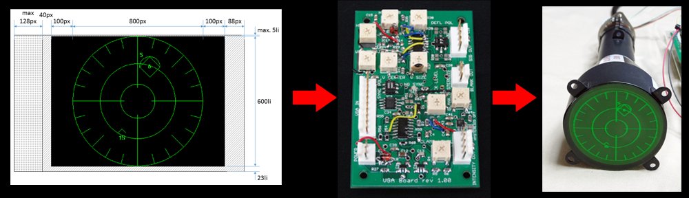
Take a look at the diagram below of the raster image I wanted to display, as it appears via an 800×600 VGA signal. See how much dead space there is, particularly at the left and right sides? This space is specified in the VGA standard as sync pulse, front porch, and back porch timings, to allow time for the display circuitry to prepare for processing each line.

A further complication (can there be more?) is that we want to display a circle in 800 x 600 (a 4:3 aspect ratio), on a round screen (a 1:1 aspect ratio)! After converting all the above dimensions into a 1:1 aspect ratio, and expressing in inches for convenience, we arrive at this:

And THUS we conclude that the beam must travel a maximum of +2.525″ to the right, and -3.325″ to the left, to make the actual radar image’s circle travel +/-1.5″ and touch the edge of the screen. And a -3.325″ deflection on the X axis (“Deflecting Plates 1-2”) at 198V/inch equates to no less than -658V ! Oh, my poor, poor +/-200V Deflection Board…
Stuck – But NOT beaten!
After hours of fretting, I hit upon a brilliant idea. Here are the facts:
- Looking at the VGA diagram, most of the dead space is in the X direction. The Y direction has very little dead space.
- Looking at the CRT specs, the deflection is more sensitive at “Deflecting Plates 3-4” than at “Deflecting Plates 1-2”. This is because 3-4 are closer to the electron gun than 1-2, and at that location the electrons are moving more slowly.
- Because the closer plates 3-4 are more sensitive, nearly all oscilloscopes apply the VERTICAL signal to these plates. And blindly following this convention, I, too, was planning to assign the Y output to these plates.
- BUT in a VGA display, neither vertical nor horizontal signals are high frequency! And, the two signals have the same amplitude (0-5V), so deflection sensitivity doesn’t really matter.
So wow! Hang convention – Why not apply the troublesome X output, which needs way more deflection than Y in order to overcome the dead space, to the more sensitive plates 3-4? And then simply rotate the tube 90 degrees!
Let’s do the math again…
3.325″ deflection on the X axis using the more sensitive (“Deflecting Plates 3-4”) at 140V/inch (worst case) equates to -466V! This is a fantastic improvement over -658V. But it’s still much more than the +/-200V my Deflection Board could deliver….
Healing the Deflection Board
Oops – I’ve run out of space for this post – and you, dear reader, have run out of patience.
Keep your eyes pealed for Part 2 – where we’ll take a look at the basic circuit of the Deflection Board, try to understand WHY it wouldn’t track more than +/-200V linearly, and finally see how I resolved the limitation. Challenge after challenge after challenge!