Yes, you’ve all thrown away your lunky old CRT monitors, in favour of sleek ultra-thin LCD displays. And, you thought you’d never see another one again…
But this CRT display has a twist! It’s round. It’s small at just 3 inches diameter. And it’s awfully cute.
Last year, I was approached by a dedicated flight simulation enthusiast, who needed a radar indicator to use in a fighter cockpit replica. The indicator should employ a CRT, for the most realistic look. Could Oscilloclock design and construct such a display?
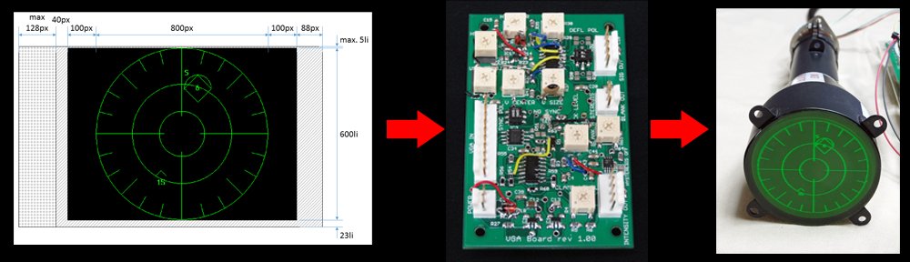
It didn’t take much convincing! Diverging only temporarily from building clocks, I took up the challenge to create my first raster-scan CRT display unit. In the ensuing months, difficulties sprang forth from every direction in the project, but ultimately I was able to avoid a diraster (sic) and deliver a functional assembly:
The key component of this setup is a new prototype VGA Board that converts a VGA signal into analogue X and Y outputs. Both analogue intensity and binary blanking outputs are provided.
Oscilloclock VGA Board prototype
The X and Y outputs drive an Oscilloclock Deflection Board, while the binary blanking output drives the blanking amplifier in a CRT Board. Blanking isolation, heater, and HV supplies are provided by a Power Board.
Deflection Board – modified for ultra-linear HV outputCRT Board – modified for improved frequency responsePower Board – with improved optocoupler
It all looks so easy! But noooo. Astute readers will recall from other posts that every Oscilloclock project involves sleepless slumbers, horrific hair-pulling, and forgotten family members. Let’s see what caused me grief this time…
Television broadcasting has switched from analog to digital – and if you’ve got a nice HD TV, you’ll be loving it!
But with that transition came the death of an entire breed of equipment – the Vectorscope.
Just to be clear, these are not monitors for playing ancient video games using vector graphics!! No, the Vectorscope is (was) used to give a delightful view of the ‘vectors’ inside an NTSC or PAL video signal, describing the color components of the signal.
If you were lucky enough to be a TV broadcast technician, you’d use your Vectorscope all the time to check your vectors’ amplitudes and phase. You would even give your vectors names like ‘Jack’ and ‘Jill’, and check up on their relationships daily, just as any responsible guardian would!
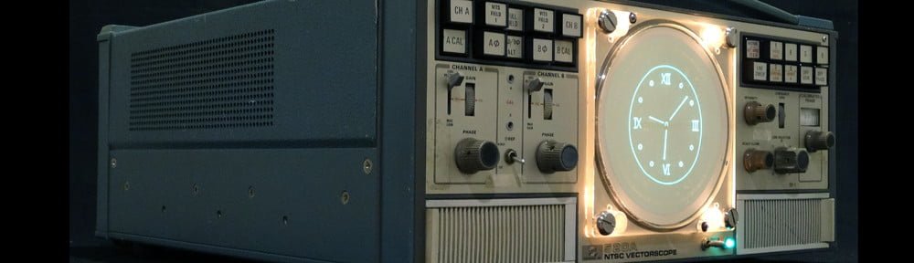
But above all, you would marvel every single day at the beautiful hardware you were using, and the complex circuitry involved. Take a look at my Tektronix 526 Vectorscope, which has oodles of delicious tubes to heat my shop on a nice winter’s day:
Well, it all went digital and there is no longer any need for analog color signal analysis. But dry your tears… There is something even better:
Announcing the Tek 520A VectorClock
This lovely Oscilloclock reincarnation of a Tektronix 520A, sold at Maker Faire Tokyo 2013, allows its new owner to forever relive the magic of NTSC, PAL and SECAM analog color.
Tektronix 520A VectorClock – brilliant blend of the old and new!See more related videos on my YouTube channel
The Tektronix 520A has a stunning built-in array of lights for illuminating the CRT graticules. By simply removing the bezel and external graticule, the Tek 520A morphs into a deliciously moody timepiece!
Normally, I shun CRTs with built-in graticules. Their lines detract dreadfully from an Oscilloclock image. But here! The Tek 520A’s internal vectorscope graticule is round! What better way to accentuate a Circle Graphics driven display?
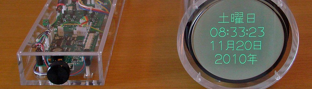
The Tek 520A is solid-state. It can be left on 24 hours a day and not fail for many years. This makes it a perfect match for my Maximum Re-use + Minimum Invasion policy: nearly all existing circuits – HV power supply, deflection amplifiers, blanking – are put to use, with just a few (reversible) tweaks.
The Oscilloclock Power Board is mounted neatly next to its own dedicated low voltage supply. A small relay board can be seen below, for controlling the Tek’s main power unit. All cabling is HV-tolerant and neatly fastened with high-temperature cable ties.
Of the more interesting reversible ‘tweaks’ needed for this retrofit, here we see a delightful little trimpot pretending to be a transistor. Quite an act, I would say!
Like what you see?
If you love big, looming Vectorscopes and need to have one put to good use in your living room, Contact me. And be sure to subscribe from the front page, to track all the other exotic experiments and unique timepieces targeted for 2014!
Credits to [Quinn] in Canada, for providing the initial inspiration for the Tek 520A VectorClock project!
The world-renowned Santa Claus. How does he get in your house to deliver presents? Does he go down the chimney (if you have one)? Does he shrink and squeeze under your door? Of course not! What silly ideas.
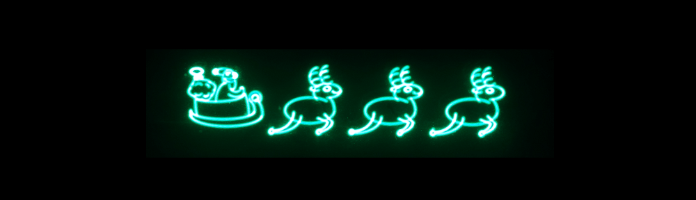
Santa simply converts himself into pure energy and beams in!! I’ve seen this glorious event myself, and now you can too – with the latest Seasonal Treats enhancement from Oscilloclock.com.
Beam me in, Santa!
Not only can you watch Santa on his travels, but you can even control where he drops his presents! Can YOU help him deliver the gifts?
Summer is over! But even as cool weather sets in, the Oscilloclock.com lab is smoking hot, preparing for…
Visit the Oscilloclock.com booth, and check out the luxury 2013 edition Model 1S – to be announced in this blog at end October. One unit will go on sale at the event!
In Transformer Corner Part 3, I looked at how to choose materials for a custom HV transformer. One way was to pull stuff from the junk-box – I did this in my early Prototype. The much, much better way was to use an off-the-shelf core with documented specs.
Let’s look at winding up the transformer. It’s amazingly easy to get a workable result!