Many folks have asked whether screen burn-in, or phosphor burn, is not a problem. They are concerned by what was a frequent occurrence in the CRT monitors and oscilloscopes of yesteryear: a permanent scar prominently visible on the screen…

To understand why this occurs, first think of an iron burn. If you deliver too much heat for too long into the same spot, your nice new Oscilloclock brand T-shirt will feature a prominent (and permanent) mark as shown below.

(I could push for another analogy, and describe livestock branding – but I think you get the message.)
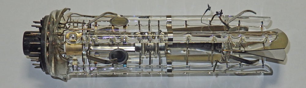
In a CRT, a beam of fast-moving electrons bombards the phosphor coating on the screen to produce an image. If the beam is too intense, or it is allowed to trace the same route on the screen over a long period of time, the phosphor compound may degrade and lose its luminance. The end result is:
- The screen won’t light up well in those spots any longer.
- The damaged areas may appear dark even with the power off – a ‘ghost image’.
Interestingly, this damage does not actually shorten the working life of the CRT! (It does not affect the longevity of the heater, or the amount of gas permeating the vacuum.) However, it is certainly not attractive, and is most definitely NOT an effect you wish to observe on your fancy custom-crafted Oscilloclock…
Keeping the ghosts at bay
Happily, screen burn-in is not much a problem with the Oscilloclock. Let’s see why.
1. CRT selection
Some CRT types and brands are more susceptible to screen burn-in than others. There are a number of factors for this, and all of these are considered during CRT selection to minimize the risk of burn-in:
First, there is the phosphor compound used. Some phosphors, just by their chemical makeup, degrade faster than others. More significant, though, is the fact that some phosphors require more energy (electron beam intensity) to produce the same level of visible light output as others.
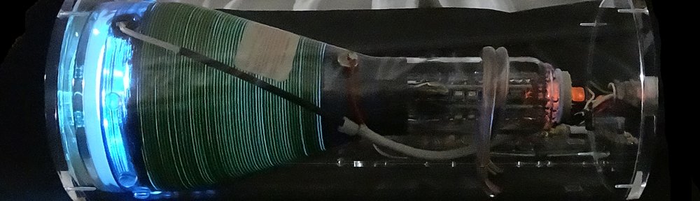
For example, a long-persistence blue P7 phosphor, such as used in the Model 1-S and the Prototype, is by its nature ‘darker’; it requires a higher beam intensity than the crisp green P1 or P31 phosphors used in many other models. The higher beam does make the P7 more vulnerable to burn-in.

Fortunately, the simple protection mechanisms in place in the Oscilloclock (we’ll get to these later) will avoid burn-in even on sensitive phosphors. The customer need not be concerned about this risk factor, and can select any of the available phosphors.
The second factor is the thickness of the phosphor coating. The thicker the phosphor, the less burn-in for the same beam intensity. Some CRTs are infamous for having ridiculously thin phosphor coatings, making them extremely susceptible to burn-in. Sadly, some CRTs that are most readily available today fall into this category, and their data sheets even specify an incredibly short maximum longevity of 1000 hours. That’s less than 2 months of continuous use!

Most CRT manufacturers did not publish lifetime ratings, nor did they publish specifications of phosphor thickness. In the Oscilloclock lab, I rely mainly on my and others’ experiences with the manufacturer, and pick and choose only the highest-quality CRTs. Expensive – but definitely worth it!
The third factor is the use of any additional technology in the CRT that would allow for reduced beam intensities. The most common example is the aluminized screen, an additional coating on the rear of the phosphor. This coating reflects the light that would normally emanate from the phosphor towards the rear of the CRT, back into the phosphor (and the front of the screen). A much more efficient use of energy!
However, this technology was a later development, so many CRTs with an aluminized screen tend to be rectangular and have an in-built graticule. These may not be as visually pleasing in a standard Oscilloclock as non-aluminized CRTs.
2. Software (Firmware) protection mechanisms

(Image used under Fair Use terms)
Remember the phrase “screen saver”? In the pre-LCD monitor days, most computers employed some form of software that would stop the same image being displayed for too long, to avoid screen burn-in.
While there is nothing as fancy as flying toasters, the Oscilloclock has several mechanisms in place.
- Hourly XY Bump screen saver
This feature simply shifts the image by a small amount in the X and Y directions every hour. The shift pattern repeats every 31 hours (a prime number), to ensure that every hour numeral will be placed in every screen position. - Auto screen switch
This feature simply cycles through the screens (clock faces) at regular intervals, configurable from 0 (off) to 90 seconds. This is by far the most commonly enabled feature, as it allows one to enjoy all the Oscilloclock screens without touching the control! - Auto power off
Strongly recommended by Oscilloclock labs, this feature simply turns the Oscilloclock off after a period of non-activity (not touching the control), configurable from 0 (off) to 90 minutes.This may sound counter-intuitive, but in practice, nearly all Oscilloclock owners are comfortable to turn their unit on just when they intend to enjoy it, and allow it to switch itself off. The exceptions are clocks that are permanent fixtures in offices and restaurants, in which case the owners manually turn their clocks on and off together with other appliances in the premises.
These features are of course highlighted in the Operation Guide that accompanies every Oscilloclock.

Summing it up
So there we have it – there’s not so much to be concerned about after all. While CRTs do have a delicate phosphor coating, by selecting a decent CRT in the first place and looking after it in use, the risk of screen burn-in is drastically reduced. In fact, in 7 years of constructing Oscilloclocks, as of today not a single unit has come back for a CRT replacement!