
Today’s story began with a mail from [Eric], who’d read up on the Oscilloclock 3-inch VGA Assembly and wondered if it could be used to create an old-school serial terminal display on a vintage oscilloscope CRT.
Yes it could! In fact, the Oscilloclock Lab did one better. Instead of just a VGA display controlled by an external device, we developed native terminal firmware that accepts DEC VT52 compatible commands over a serial port, and renders all text and graphics using beautiful, curvy Lissajous figures.
The stuff of dreams. The OscilloTerm Exo B7S4.


Zork, anyone?
Ultimately, [Eric] just wanted to play Zork. And together we made it happen.
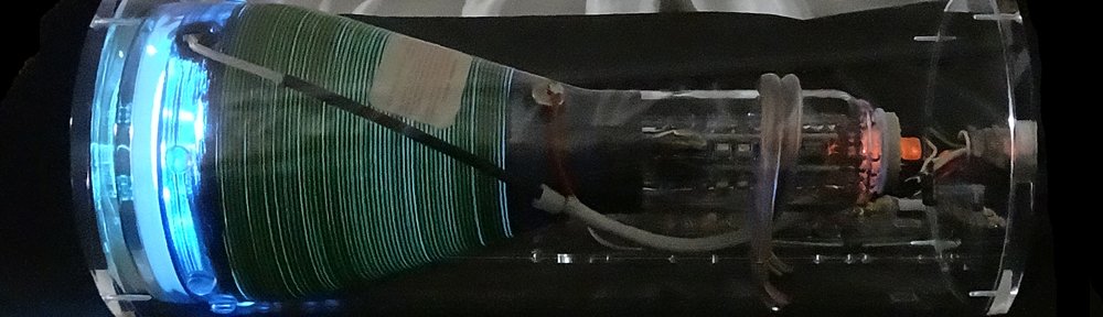
The CRT. The Case.
[Eric] wanted a sleek ‘skeleton’ look. His choice of a gorgeous B7S4 CRT, mounted in custom-machined cast acrylic supports, exposes all glassware and allows for a titillating rear viewing experience.

And with a high-transparency cast acrylic case housing the electronics, the OscilloTerm Exo can be enjoyed from every angle!


Astute readers may wonder about the 2.1 kilovolts of high voltage coursing through their innocent-looking device. Rest assured! All internal wiring is sealed off, and Oscilloclock CRT harnesses are hand-crafted with heavy insulation and precautions taken against dust, prying fingers, rats, and even salivating cats.


This case and CRT mounting variation is branded the Oscilloclock Exo, and has proven its wow-factor at several public exhibits to date. We certainly love it, and [Eric] did too!
The Terminal.
This post would never be complete without showing you what real serial terminals from the 1970’s looked like, and explaining what they actually did! Here goes…

ClickRick, CC BY-SA 3.0, via Wikimedia Commons

Terminals such as the above were physical input/output console devices, back when computers were the size of massive refrigerators, and the operator would sit remotely – at a desk in a separate area, or even a different room.

The terminal and the remote computer were connected via a cable, and would communicate each other by sending data back and forth across the cable; mainly terminal commands and ascii encoded text. Most commonly, a serial communication protocol was used to get the data safely from one end to the other – and hence the devices were known as serial terminals or even serial consoles.
Amusingly, they were also called dumb terminals, because they had no computing power of their own; they were only extensions of the computer to which they were connected.
The OscilloTerm Terminal.
[Eric] wanted a special Oscilloclock that he could also operate as a terminal, connecting it to a remote computer via cable. The remote computer would control the display, using the same serial protocol and commands as an ancient dumb terminal.
But an Oscilloclock is anything but dumb. [Eric] wanted to keep all the standard exciting screens and features of his Oscilloclock active, and only display the special Terminal screen when the remote computer started to send commands. Then, when the commands stopped, the Oscilloclock should go back to the screen it was on!
His wish was our command! Here’s a demo of smart screen switching in the final product:
Some technical Comments
Naturally, the terminal emulator firmware was written entirely in assembly language.

We use assembly mainly because the minimalist PIC microcontroller used in the current Control Board revision has only 64K ROM, and an unbelievable 3328 bytes (yes, BYTES!) of RAM. To squeeze all the lovely Oscilloclock features in, while driving Circle Graphics real-time processing, the code and memory space has to be clean, tight, and heavily optimized at the machine code level.

For even more technical details, such as the list of VT52 (and VT100) commands supported by the OscilloTerm, and the various configuration parameters that can be tweaked to make the terminal emulator more ‘friendly’ when connecting to a specific device, check out the Support page. Worth a visit!
Why Zork? And HOW?
Zork is an interactive adventure game. But it’s old. And it’s text-based, because it was run on computers long before fancy graphics capabilities were widely available. The player explores mysterious locations, solves puzzles, and collects treasures while avoiding various hazards and creatures. All by reading text and typing commands and responses!
[Eric] was able to play Zork by loading the game’s Z-code into a Z-machine interpreter known as Frotz, on a PC connected to the OscilloTerm. But there was trickery involved!
- He had to recompile a version of dfrotz (the dumb terminal version of frotz) to remove the status bar and audio from the game.
- He needed to wrap the dfrotz output with a custom Python script to support the OscilloTerm’s 16×8 screen and simulate the required baud rate.
But now that’s done, he can play any Infocom game that runs in dfrotz on his OscilloTerm!
What’s next?
Readers would probably agree that adding a generative AI feature would be incredibly cool. For example, the War Games feature is great, but the text on the screens is all pre-programmed. What if you could interact more naturally with your Oscilloclock?
Another one for the list!
Are you a serial serial terminal collector? Do you want to play Zork on the oddest device imaginable? Or, you fancy a clock in the Oscilloclock Exo range? Contact us and let us know!


