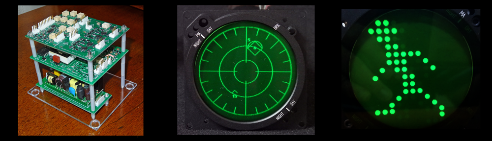
It’s been a long while since I wrote about the 3″ VGA Display assembly, which was used for an RWR indicator in a fighter cockpit simulator.
The customer came back and requested four more. But could I stack the boards to make the units more compact? Of course!!

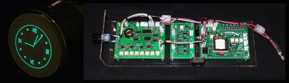
This particular assembly is rather tall because the client requested an in-built mains supply board, sitting at the bottom. The normal configuration using an external power pack is half the height. (In which case it’s not quite a “cube”…)


And if you aren’t into aircraft indicators, you could always have a bit of fun!
Is a VGA Cube right for you?
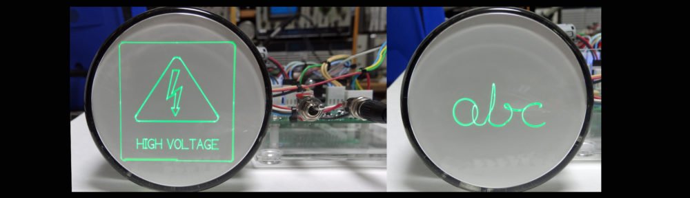
Maybe. Or maybe not! These units incorporate binary blanking – I.e. The beam is either on or off; no shades of grey. Hence any VGA image composed of thick line art like RWR will display well, but shaded or coloured displays such as an attitude / horizon indicator would not work so well.
Below is a Windows XP login screen… Not exactly a flattering image!!

VGA Board – better and better
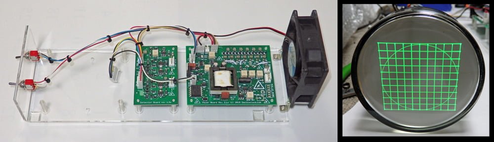
The latest VGA Board rev 1.1x is small and cute, and is compatible with the standard Oscilloclock Deflection and Power Boards.
In keeping with tradition, the VGA Board employs entirely analogue techniques to generate the horizontal and vertical sweep, triggered by incoming sync pulses. A high-speed analogue comparator with adjustable levelling is used to convert analogue RGB into binary blanking. Naturally, inputs are ESD protected so you can’t easily blow the chips!

Like what you see?
VGA Cubes are like any other Oscilloclock product – each unit is hand-crafted to order and fully tested so that I can optimise for the selected CRT and provide a decent satisfaction guarantee. To date I’ve made five – and always happy to discuss a sixth! If you have a passion for raster rendering, let me know!