A few months ago, [Andrew] – of Metropolis Clock fame – reached out for help. He had just pulled his lovely Oscilloclocks out of storage to put on display, when he observed odd behaviour in both units: the time was accurate, but the date was stuck – to some random date back in 2003!
What on earth was going on?
What’s going on was not “on Earth” after all! [Andrew]’s clocks synchronise time and date against satellites, using an external Garmin GPS unit. And this unit happened to have a serious flaw. In this series of three articles, we’ll look closer at this accessory, identify this issue, and see how we were able to resolve it. Enjoy!
Our longevity dream
We want your Oscilloclock up and running as long as you are – and even beyond! Our dream is to see these beloved devices inherited by loved ones, and even available on the second-hand market as antiques one day.
In an era of throw-away technology, we flaunt an unthinkable target: Decades of trouble-free* operation.
* Excluding the CRT itself – although we really try hard with that as well, as this post explains!
To maximise usable lifetime (and safety!), we construct Oscilloclock units from the finest materials and components available. As part of this, we also select manufacturers that guarantee their components and provide decent after-sales support.
And Garmin is one such manufacturer…
Welcome to the Garmin GPS ‘Puck’
All Oscilloclock models that synchronise time using an external GPS unit have so far been supplied with a Garmin 18x LVC GPS unit, colloquially known as a ‘puck‘. (Note: to extend the lifetime of the pucks, we do not recommend using them on the hockey court.)
Now, this is not the smallest external GPS unit on the market today. But it has been available from Garmin since 2007, and is even being manufactured today! It is one of the most sensitive, robust, and well-supported units out there.
(Of course, for every new Oscilloclock delivered we evaluate afresh based on the latest devices available.)
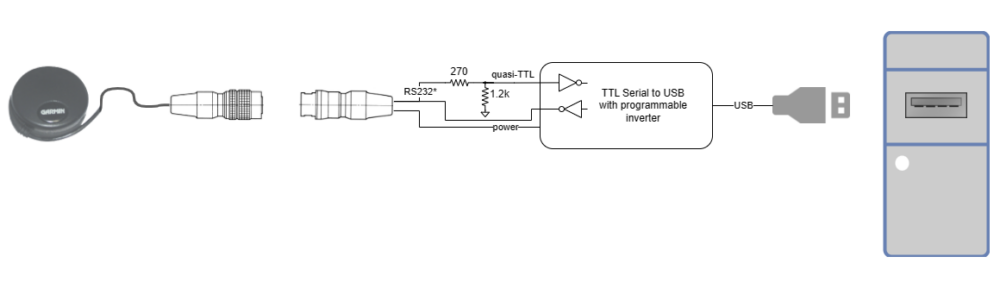
This puck has a special connector …
How many times have you relegated an expensive laptop, phone, or other random device to the trash just because the power socket or headphone jack failed? Some of the weakest components of any electrical device are its connectors – plugs and sockets.
To combat such failures, your puck is wired with an exceptionally high quality connector from Hirose. This connectivity solution is not only robust, it even feels good! There’s a lovely audible and tactile ‘click’ when you engage the plug, and it locks securely in place. And unlike cheap chrome-plated connectors, we’ve proven that these babies do NOT corrode, even after a decade.
Whether directly or indirectly, the pandemic seems to have slowed everything down: chip production; the global economy; and even Oscilloclock blog post publishing!
But perhaps most impacted of all is transport logistics. [Dante] in Brazil discovered this to his dismay in July 2020, when he purchased an Oscilloclock Bare unit. The P.O. had stopped all air service to Brazil just 3 weeks earlier – well after our discussions had started. Oh no!
[Dante]’s crisp new Oscilloclock Bare, ready to go, but unable to ship!
[Dante] waited patiently for 6 months for the post office to resume accepting airmail service to Brazil. But they never did. And FedEx and DHL came at too hefty a price. In desperation, he authorized shipment by sea – and at last, in December 2020, his package was off!
Absence (of air mail service) makes the heart grow fonder...
After an agonizingly long wait, [Dante] finally received his unit 6 months later – in July 2021. He then spent the next 5 months completing his dream project!
[Dante]’s Dream: A Hewlett Packard retrofit
The Oscilloclock Bare is designed to be a no-frills controller assembly that highly knowledgeable folks can install into their own displays. [Dante]’s dream was to use this to convert his beloved HP 182T / HP 8755C unit into a living, breathing scope clock.
And convert he did!
Question: How do you add ambience to a home? Answer: Instill new life into a device from yesteryear!
Clearly, [Dante]’s 18 month end-to-end was worth the wait.
The Build
[Dante] was kind enough to supply a write-up of his project, including some clever solutions for pitfalls along the way. Let’s hear from him in (mostly) his own words!
Motivation
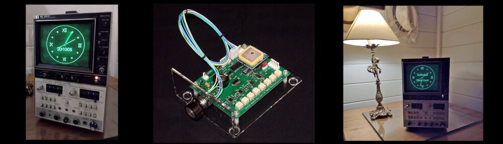
The model HP 182T is an oscilloscope featuring a large CRT with a graticule of 8 x 10 major divisions and a display area of 133 cm2, coated with a P39 aluminized phosphor for high brightness and long persistence.
The HP 182T works as a display mainframe supporting other HP plug-in test equipment, such as the HP 8755C, a swept amplitude analyzer.
Both items are nowadays considered “vintage” test equipment. But with the Oscilloclock board installed, they have been transformed into a unique appliance with a natural appeal for practical use. Far better than the regular surplus market destinations, or — even worse — destructive disposal!
HP 182T + HP 8755C. Can you spot the Oscilloclock control board?Control board installed!
HP 8755C in short
This plug-in unit works primarily as a signal conditioner and a multiplexer for “almost dc levels” from three RF detector probes attached to three input independent channels. There are front panel adjustments for the scaling, gain and multiplexing controls that provide the appropriate Y-Axis composite signal for displaying by the HP 182T mainframe.
The Oscilloclock control board was elected to be installed inside this plug-in unit.
HP 182T in short
This oscilloscope is built around the CRT with its high voltage power supply.
The X-Axis signal from the Oscilloclock board is fed to the HP 182T’s chain of the horizontal pre-amp plus output amplifier, which drives the CRT horizontal deflection plates.
The internal wiring of the HP 182T connects the CRT’s vertical deflection plates directly to the plug-in cabinet of the display mainframe, so the Y-Axis signal from the Oscilloclock board is routed inside the HP 8755C itself.
The Z-Axis signal from the Oscilloclock board is fed to the HP 182T’s gate amplifier.
Wires, wires…. What goes where?
Drawbacks
Contrary to any standard X-Y scope where the two input channels are always supposed to have electrically similar (if not identical) characteristics, the correct operation of the Oscilloclock board for the application here was shown to be not as seamless as first imagined. You have to face some details of these integrated “host” equipment (HP 182T + HP 8755C) to see why…
As described, there are distinct amplification chains accepting the Oscilloclock output signals. This presents specific challenges regarding (a) the differential gain for the X and Y signals, and (b) the differential time delay between any combination of the three X, Y, and Z signal outputs of the Oscilloclock board.
First Approach
Before having the board at hand and expecting to make it work as soon it arrived (the shipping took longer than expected due to COVID restrictions), I first planned the signal flow and did the wiring. I had one eye on achieving a ‘clean packaging’ of the board inside the HP 8755C, and the other on ensuring compatibility between the Oscilloclock’s X-Y-Z output signals and their respective chains planned in the host equipment, considering signal amplitude and required frequency response.
The adaptations made at this time considered a minimally-invasive approach, where the criteria was to “make it simple”. This was limited to just opening or re-using connections and keeping the existing routing, in order to use the Oscilloclock’s X-Y-Z output signals in the most simplistic way possible.
Another necessary one-time adaptation was for the board’s power supply, and integration of its PSON output signal with the equipment’s hardware. This part of the design was successfully kept to the end of the project without any further modification.
First time installation of the oscilloclock board
Upon arrival and a bench test of the Oscilloclock board with a scope, I immediately figured out that the amplitude levels for the X and Y output signals were lower than expected (maybe due to my misinterpretation of the specs). I did the gain compensation corrections again and went thru the complete installation of the board inside the host equipment, anxious to see it working.
What a disappointment when instead, up came a completely distorted and elliptically shaped image, blurred with noise, and what looked like un-blanked retrace lines. Worse yet, mainly when alphabetic characters were displayed on the screen, none of the shapes were correctly formed.
Of course, that was time for a break — and a complete review of the job and the work done so far!
Chasing the problems
The Lissajous figures generated by the Oscilloclock board use an approximately 40 KHz sinusoidal signal, so I started to play with an external generator at the same frequency and amplitude for the X and Y signals (at about 1 Vpp) and trace it inside the HP 8755C and HP 182T.
At this time, I’d already exercised the Z-axis waveform from the Oscilloclock board and the expected processing through the HP 182T. There was no evidence of problems with this Z-axis signal chain, and I achieved a measured propagation delay of around 50 nS.
The minimalist approach mentioned earlier showed its consequences, when a propagation delay of an impressive 8 uS was measured at the vertical deflection plates, and around 1.5 uS at the horizontal deflection plates! It was time again for another break, to elaborate a new routing scheme for the X and Y signals.
Final Approach
From the previous analysis, I ended up with two different and both very large propagation delays for each of the X and Y signals (as compared with the measured 50 nS for the Z-axis). How to solve this? It did not seem to be only a routing problem.
I decided to investigate X-Y-Z signal propagation delays in the two units separately. After a thorough measurement of propagation delays inside the HP 182T itself, comparing with the HP 8755C plug-in itself (where the Oscilloclock board was installed), I concluded on two countermeasures:
1. The complete removal of the Processor board XA-6 from the HP 8755C. (This is where the Y-axis signal from the Oscilloclock board had initially been connected.) Instead, this routing was transferred directly into the Normalizer Interface board XA-11 (which interfaces with the HP 182T).
2. Also at the Normalizer Interface board XA-11 inside the HP 8755C, the substitution of two original op amps U9A and U9B (HP #1826-0092) by TL072 op amps, which are faster and have a higher slew rate.
These solutions were enough to align the signal propagation and complete my project!
Dante JS Conti, 8 November 2021
Like what you see?
We do! We love to hear back from Oscilloclock owners, to hear their stories.
Check out our previous posts and the Gallery for info on other unique creations!
Q: “What’s your New Year’s Resolution? A: “Why, 1024 x 768, of course!”
Geeky jokes aside, here at the Oscilloclock lab we DO have a form of New Year’s resolution! 「日進月歩」Nisshin-geppo, which loosely translates as “Steady progress day by day“, reflects the goal to complete the the once-in-a-decade re-design work, and resume crafting beautiful Oscilloclock products. It also highlights confidence that issues currently facing the wider world will be overcome, one step at a time.
In keeping with local traditions, [Oscilloboy] wrote the slogan in Japanese calligraphy. But there, tradition ended and true joy began! Behold, courtesy of an Oscilloclock VGA Core assembly, Oscilloclock’s 2021 New Year’s resolution on a beautiful old 7-inch oscilloscope!
The Setup
After choosing an appropriately meaningful four-character phrase for our resolution, I asked [Oscilloboy] to write out the characters. Bucking with tradition, we used standard white A4 paper instead of calligraphy paper. The ink took more time to dry, but we wanted to maximize the contrast.
[Oscilloboy] demonstrates his prowess in Japanese calligraphy. Right: the finished product!
After scanning the handwritten characters and inverting the images, I created a rolling video in 1024 x 768 resolution. (See? The joke at the beginning of the post about resolution was serious, after all!)
I then played this through an Oscilloclock VGA Core assembly, which is essentially a graphics card that allows you to use a beautiful old CRT as a rudimentary computer display. (For earlier write-ups, see VGA display… On a 3″ scope tube! and The VGA Cube! .
The assembly used here features a late prototype of the Revision 3 Power Board, which I have been working on for almost a year. I won’t go into all the bells & whistles yet. Stay tuned!
A VGA Core assembly – displays monochrome images from VGA, SVGA and XGA inputs
Unlike a permanent Oscilloclock conversion (see the Gallery for examples), this was only a temporary setup. The VGA Core was positioned externally, with the harness routed into the 7VP1(F) CRT via the rear of one of the side panels. No invasive procedures needed!
Just LOOK at that beautiful CRT socket – brown Bakelite!
No VGA socket on your ultramodern slim notebook of choice? No problem – use an off-the-shelf HDMI to VGA converter!
And voila – the final result! Japanese calligraphy on a vintage 7″ oscilloscope!
About the Model – A rare 1963 Nitsuki Oscilloscope
Nitsuki is the brand name of Japan Communication Equipment Co., Ltd., a specialist in television and microwave broadcasting systems. The firm’s English name was originally Nihon Tsushinki Co., Ltd., so you can see how the Nitsuki moniker came about.
Check out this exquisite cap on the pilot lamp!
By 1963, the Japan domestic test equipment market was mature and quite competitive. English language labeling had become stock-standard. This scope is one of very few units I have ever obtained that has Japanese labeling. How appropriate for today’s display!
Japanese labeling – a rarity!
Some of the higher-quality oscilloscopes of this era featured flip-latches and detachable side panels, for easy access. See the Toshiba ST-1248D for another example. These scopes are infinitely more enjoyable to work with and show off than scopes with a slide-out chassis.
This model is also quite unusual for its time in that most of the components are located under the chassis! The valves (tubes, if you prefer) are even mounted horizontally. Nitsuki used very robust construction techniques, including very tidy cable lacing.
In fact, their design was so robust that the scope functions almost perfectly today (except for some triggering instability), yet there is no evidence of major repairs in the last 57 years!
Back to its natural self – a nice old 7-inch 1963 oscilloscope!
Like what you see?
The Oscilloclock lab struggled in 2020 due to worldly events, but NOW – day by day, step by step, the newly designed Oscilloclock boards are at last taking shape! Does your New Year’s ‘resolution’ for your next project specify 1024 x 768? Or perhaps you’re into displaying fancy calligraphy on vintage CRTs? Let me know.
And as always, see previous posts and the Gallery for info on other unique creations!
Critical Update 25 December 2021
Well. Christmas Day 2021, and [Oscillowife] — the chief editor, advisor and critic extraordinaire — just informed me that I had placed [Oscilloboy]’s first character「日」upside down when creating this post! Apologies to our readers for the gross oversight.
It’s been 12 months! But better late than never to eat humble pie…
In a desperate attempt to save his blog from becoming the all too familiar not-updated-in-5-years dead blog, the senior technician has resorted to seeking help from one of his sons, previously referred to as the 1st junior technician. Although my knowledge on CRTs and electronics is close to none compared to that of the senior technician, I will give you some updates on the recent activities of the main man himself, who I am sure all of you are eagerly awaiting the return of.
Amid the COVID-19 crisis, the senior technician has been lucky enough to be able to work at home. You would think that without his everyday commute of two hours, he would be more relaxed and able to spend more time with his family members. However, he is instead spending excessive time in front of the computer. At first, I speculated that he was having a rough time with his work. Or was he? Under closer examination, I realized that the additional time spent on the PC was actually something related to Oscilloclock. Something about a brand new design: “once-in-a-decade refresh,” and some such. Not really sure how significant this is to you all, but judging from the look on his face when he emerges from his room for dinner, it must be something BIG!
Another clue that the Oscilloclock Lab is heavily active is the vast array of international deliveries to our home in the past half year. Shipments from countries that you’ve never heard of, in all shapes and sizes, arriving so frequently that I can’t help feeling for the poor postman who has to carry these heavy objects up to our door. I must tell you, there is nothing worse than hearing the bell ring and rushing down to the door anticipating your own Amazon delivery of a new pair of shoes, and instead seeing a massive box from Montenegro containing who-knows-what-type-of-CRT.
The master craftsman’s work could very well be hindered by the noise from his two highly energised teenagers, [Oscillokid] and [Oscilloboy]. So how does he maintain concentration? The secret is a well-positioned cave. His workshop is intentionally situated at the very edge of the house. He simply closes the lone door to the shop, to avoid hearing a dinner-call or a request for more screen time from his Oscillosons. Until, of course, the commander-in-chief of the household raises her voice!
So there it is, a brief update on what’s going on and how the senior technician’s doing. Rest assured that he is working very hard on his projects, and has not in the least swayed from his passion; indeed, he is more immersed than ever. He will no doubt inform all of you anxious readers of his magnificent projects once they are ready for exposure. Until then, thanks for reading, and stay safe!
These days, just about everyone has an old oscilloscope lying around. You know, an old, dusty, derelict scope handed down from Grandpa (or Grandma). Well, [Paul] had something even better – an old Tektronix 602 X-Y Monitor! Could an Oscilloclock Control Board drive this vintage beauty? Absolutely. Could I make an aesthetically pleasing case? Definitely. How about time sync via WiFi? Stock standard!
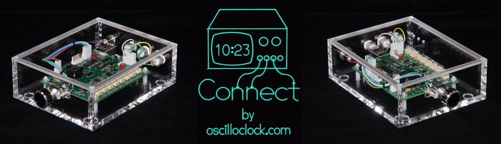
Presenting the Oscilloclock Connect:
Here’s what it looks like plugged in to my fabulous old Tektronix 620 monitor:
And why not have a pair of Connects drive a Tek 601 and 602?
The Build
The main component of the Connect is, of course, a standard Oscilloclock Control Board. As usual, all 121 parts on Paul’s board were individually mounted and soldered by hand. The board then was programmed and underwent rigorous inspection and testing. Finally, the board was cleaned to remove flux and renegade flecks of solder, and sprayed with HV coating for humidity protection and – arguably more importantly – to give it its glorious sheen.
The case was custom-made and professionally machined right here in Japan from 6mm-thick sheets of pure cast acrylic (not extruded). This is an extremely transparent, hard, high grade acrylic – and Oscilloclocks deserve nothing less!
The case was sprayed with a special acrylic cleaner and static protection solution, before fitting the various components. Naturally, every part was cherry-picked, right down to the three BNC connectors – they needed an aesthetically pleasing colour, but they also had to have a shaft long enough to mount through 6mm-thick acrylic!
Finally, the physical interface! The knob was chosen for its perfect finger-fit and delicate aluminium/black tones, which gently contrast with the rest of the unit.
The Compatibility Crisis
Over the years, many folks have observed that the scope at hand has an “X-Y mode”, and asked if they could just ‘plug in’ an Oscilloclock Control Board. “Is it compatible?” Unfortunately, the response has usually been disappointing.
You see, creating figures and characters with Circle Graphics relies on the scope’s ability to turn the beam on and off at split-second intervals. This feature is called a “Z-axis input”. While many scopes from the 80’s and beyond do sport such an input, there are two common limitations:
Limitation 1: AC-coupled Z-axis inputs
Capacitive coupling – effective at isolating the input from cathode potential (-1260V !)
The input is connected to the CRT’s grid or cathode circuit via a capacitor. This is a low-cost, effective way to isolate the (usually) very high negative voltage of the grid circuit from the input.
The problem here is that the capacitor, by its very nature, removes the edges from the pulse. The controller is no longer able to control the beam on/off timing, and you end up with uneven blanking across the segments, as shown in the screenshot at right.
Depending on the values of the capacitor and the surrounding resistors, the symptoms may not be severe. However, the best way to resolve this problem (while still keeping the oscilloscope’s original circuit intact) is to insert an isolated DC blanking amplifier directly in series with the grid (or cathode). See the Kikusui 537 Oscilloclock for an example of this.
LIMITATION 2: INSUFFICIENT BLANKING AMPLIFICATION
Most oscilloscopes tend to require at least +5V on the Z-axis input to noticeably blank the beam. The Connect, however, is only capable of delivering +2.5V. It works just fine if you set the scope’s Intensity control very low, but as you increase intensity, the blanking quickly becomes ineffective.
Below we have a beautiful Japanese YEW (Yokogawa Electric Works) 3667 storage scope. The left shot is misleading due to the camera exposure; the displayed image is actually extremely dim. The right shot shows the same* image with the intensity control increased – the image is bright, but there is no blanking!
* Astute readers will observe that the time is significantly different between the two shots. This is a result of the WiFi NTP sync kicking in right in the middle! More (or less) astute readers may also notice that the scope’s trace rotation is not adjusted very well…
Of course, it would be a simple matter to incorporate a pre-amplifier for the Z-axis, which would solve this problem. This will be introduced with the next Control Board revision!
Like what you see?
Nothing brings more joy than connecting this bundle of usefulness into a woefully unused old oscilloscope or X-Y monitor. If this is of interest to you, visit the Availability page for more information, and of course see the Gallery for other unique creations!