Huh? R2D2’s cousin? C3PO’s sister?
No! We’re not here to talk about a new Star Wars character! The 3KP1 is a type of cathode-ray tube that was used in many low-cost 1960s-1970s Japanese oscilloscopes.
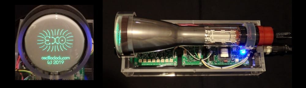
And the Exo is a series in our Oscilloclock range that fully exposes the CRT both visually and physically, much to the delight of the owner and visitors – while of course protecting high voltage areas from dust and prying fingers.
The Exo 3KP1!

First crafted for [Jerry] back in 2019, the Oscilloclock Exo 3KP1 is the default character in the Exo series, alongside the arguably oddball Oscilloblock – Summer Dusk Edition and the slightly more exotic OscilloTerm Exo B7S4.


There’s nothing more soothing than the green glow of flourescent phosphor backed by the amber ambience of the CRT heater. Ahhh, that’s nice.

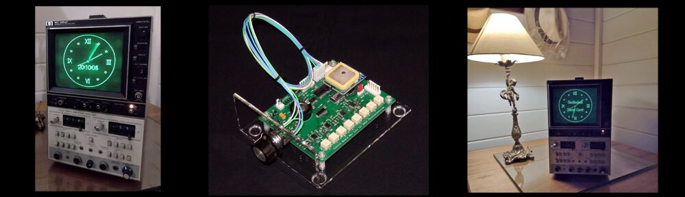
This Exo shipped with all the “standard” screens, like the analog clock face below. But why stop there? We’ve done custom logos, movie themed features, oddball time systems, and so much more!

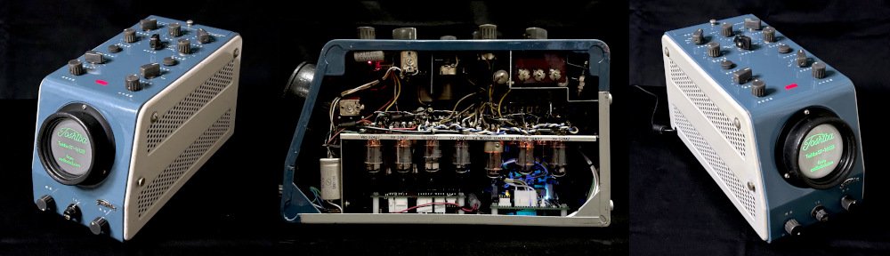
From the top, [Jerry] and his dinner guests can readily inspect every square centimeter of the CRT and its exquisite innards. Cooool.

Inside the unit, neatly tied cabling lends an air of gentle sophistication, while the green of the circuit boards harmonizes well with the phosphor.

Even as a baseline model in the series, the Exo 3KP1 is distinctly attractive.
[Jerry] did make some choices along the way, including which CRT to use. Let’s explore his CRT options in more detail!
Round vs. flat

As shown in the photos, the CRT that [Jerry] selected has a slightly convex face. This was the standard shape of the original 3KP1 type CRT, and is a perfect choice for the Exo case style, as it visually softens the glass edge exposed in front of the acrylic ring supports.
The round-faced 3KP1 was superseded after some years on the market, by a flat-faced version: the 3KP1(F). This version is rather more commonly found and they are delightful to use. We used a 3KP1(F) in the Exo series Oscilloblock, as shown at right.
Which would YOU prefer – round or flat?
Phosphors and flavours
[Jerry] had another choice to make: the phosphor! While the standard phosphor of most CRTs of the day was green, other colours were available such as amber, blue, white, purple. Such CRTs are more rare, but we have some… and so could Jerry!


There were also varieties of CRT with different persistences; i.e., how long the trace would continue to show on the screen! We love this shot of the moving second hand on a blue, long-persistence CRT:
And, we just happened to have a 3KP7 CRT in stock with exactly these characteristics.
But in the end, [Jerry] wanted the nostalgic look of an old green-screen computer monitor, and chose the stock-standard 3KP1.
Nice choice!!
The longevity question
[Jerry]’s clock shipped with a used 3KP1 CRT. Pre-owned, pre-loved, and pre-21st century.
But we don’t sell junk. [Jerry]’s CRT was selected for its unblemished phosphor, and for its still-bright and vibrant performance. And, of course, there is the standard warranty of 1 month for a used CRT:

But the question often comes: “How long will a CRT really last?”
Here at Oscilloclock we don’t mince words, and we don’t use euphemisms (much!). But the fact is this – after 15 years of crafting Oscilloclocks for customers around the globe, no-one has reported having to change their CRT. Maybe it’s happened and we are oblivious. Even better!
Our secrets to CRT longevity are:
- We select only the highest quality CRTs, made by reputable manufacturers. [Jerry]’s CRT was manufactured by Toshiba, a key supplier of the day.

- We check CRT specifications carefully, and avoid those with any hint of short lifetimes. (Some CRTs had very short expectancies, such as 1000 hours! Perhaps these were used for demanding applications where even a tiny degradation in performance could not be accepted.)

- Oscilloclocks employ multiple mechanisms to avoid screen burn-in (phosphor burn).
- Oscilloclocks employ a soft-start mechanism to minimize stress on the CRT heater.
The Spare
Notwithstanding our facts around longevity, [Jerry] decided to plan ahead for an eventual CRT replacement. He purchased a stunning new-old-stock Hitachi 3KP1, with quality certificate and even in its original box.
They don’t get more original than this!


But is a Hitachi 3KP1 better than a Toshiba 3KP1?
We’ve compared them, and couldn’t tell any difference in performance or characteristics. We did notice one thing, though: the Hitachi is significantly heavier than the Toshiba. Hmmm….
One day, we’ll dissect some (defunct) units, and get to the bottom of that odd observation. Stay tuned for a post!
Like what you see? [Jerry] did. Check out our other creations!