Recently I received a most intriguing request: I was asked to build a self-contained, super-bright X-Y display unit with 3-inch CRT, for use in an “HUD“. Hmm…
Holographic Utterance Device?
Horizontally Unstable Doohickie?
…
Fortunately, I didn’t need to guess any further. As I was once an avid flight simulator enthusiast, I quickly hit upon the correct meaning: Head-Up Display. This is a mechanism that overlays instrumentation or map data onto the view looking forward from the cockpit, so that the pilot doesn’t have to look down to see this information.

Wikipedia has a great introduction to HUDs and their history, but Mike’s Flight Deck has the definitive tome for flight simulator enthusiasts who want to actually build an HUD. According to Mike, the system employs various optical paraphernalia, but at the heart of the mechanism is what lies closest to my own heart – a CRT Display!

Key Requirement: Brightness
The CRT display used in an HUD needs to be very, very bright. The image loses its intensity as it traverses through collimators and other optical devices, and it needs to be visible even in daylight conditions. To achieve this, HUD displays used in real aircraft employ specialized CRTs with very high accelerating voltages (10-20kV).
Adding in the resilience requirements demanded of aircraft equipment, these displays go for tens of thousands of dollars, and are not easily available on the retail market. Maintenance is also prohibitive. Ultra-bright thin display technology may well replace the CRT in the near future (if not already), but such displays may be even more expensive for hobbyists to procure.
My customer needed a lower-cost, easily maintainable alternative. He had read my 3″ VGA Display article, and noted that I love to eke every spare lumen out of my CRTs. Would an Oscilloclock display be bright enough? Possibly – so I took up the challenge!
Control Requirements
The customer was building his own control board, that would generate the symbology using vector graphics (as opposed to a raster-scanned image like in the VGA display). This was great news – a typical vector image will easily appear brighter than a raster image, since the beam is turned on nearly 100% of the time.
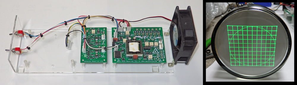
So what was needed was a standard Oscilloclock X-Y Display, optimized for deflection bandwidth and brightness. Digital blanking (Z axis) would be required as well, just in case his controller could not move the beam rapidly enough between segments to avoid a visible trace.
Board Enhancements
This was a perfect time to put in place some enhancements that had been on the backlog for more than a year! The new Oscilloclock Power Board rev 2.1x offers the following:
- Maximum cathode to deflection voltage of 2175V (max 3675V if isolated blanking is not required)
- Maximum accelerator voltage of 3525V for PDA type CRTs
- TTL/CMOS compatible digital blanking (grid modulation), safely isolated at 2.2kV continuous working voltage, 250-350ns end-to-end propagation delay
- Onboard blanking amplifier – external “CRT Board” no longer required (but can optionally be used for longer CRT harnesses)
- Support for “Deflection Blanking” CRTs (see treatise here)
- Dim/Bright and Power Off inputs
- Temperature-sensitive fan controller with Failure and Overtemp safety features
- CRT rotation coil supply (+/-5V)
- CRT heater soft start / inrush current limiting
And the Oscilloclock Deflection Board rev1.3x now sports:
- Precision deflection amplifier capable of driving +/- 275V with 0.1% linearity
- 0-5V analog X and Y inputs, gain adjustable via single resistor per channel
- Onboard 2.5V reference output
But which CRT??
With brightness being such a key requirement, a PDA (post-deflection acceleration) CRT seemed the ideal choice. However, new-old-stock PDA CRTs are not exactly plentiful on the market, and one goal of this project was to reduce maintenance costs associated with CRT replacement. The customer wondered if the more ubiquitous non-PDA type 3RP1A might be bright enough?
I thought it might, if I powered it at 2.2kV. This is the safe continuous working voltage limit of my isolated blanking circuit, and is still within the CRT’s maximum specification of 2.7kV. (If blanking were not required, we could have maxed it out – but then the deflection amplifier would need enhancement to drive even more than +/- 275V. My 3″ VGA Display article examines the relationship between deflection sensitivity and acceleration voltage.)
The 3RP1A was a great choice, and I optimized the assembly for that CRT.

3KP1(F) – an alternative to 3RP1A?
I got to thinking again about maintenance. The customer might operate his simulator for hours each day. He will set the intensity quite high. The vector graphics symbology might be fairly static on the screen. These usage factors will naturally and unavoidably lead to either the dreaded SCREEN BURN-IN, or at least CRT BURN-OUT!
What if the customer had a stable supply of used CRTs that were so cheap that he would be happy to (literally) burn through them?
Oscilloclock labs had just the thing! I regularly procure used 3KP1(F) CRTs in great condition. Electrical characteristics are similar enough to the 3RP1A. Size is not.

But what about performance? Below is a qualitative look at a 3KP1(F) against a 3RP1 (I didn’t have a flat-faced 3RP1A in the lab at the time). At the macro scale, the difference isn’t hugely obvious.

But what about brightness and line resolution at smaller scales? Let’s examine line resolution:

At this scale, the 3RP1 does appear more performant.
I configured the board to support both 3RP1A and 3KP1(F). The battle will be won when the customer tests both tubes in the actual installation. Stay tuned!
What’s Next?
Raster graphics is mediocre. Vector graphics is good. But Circle Graphics is simply stunning! Could I reprogram the Oscilloclock Controller Board to interface to a flight sim API, and display HUD imagery and symbology in silky curved figures? I could! I would! Well, okay, I might… a project for another rainy day.

Like what you see?
Are you building an HUD and need a 3″ display? Are you interested in a Circle Graphics based HUD controller? Or are you looking for a nice standalone X-Y(-Z) display for your fancy new thing-a-me-bob? Contact me – and perhaps Oscilloclock.com will take up yet another challenge!