Avid followers may have noticed an absence of fresh posts recently… What gives?
I’m happy to report that it’s only because Oscilloclock has been absolutely run off its feet in 2016, producing more crazy CRT based devices than ever before. There just hasn’t been time to do justice to the blog!
The good news here is there are lots of posts in the backlog. Let’s start out with this one:
Yet Another CRT clock fanatic?
I was approached by [Mike], who wanted to design his own CRT clock from scratch, but didn’t want to mess with the high voltage circuitry involved. Could I help out with an X-Y-Z display assembly, and he would do the rest? You bet!
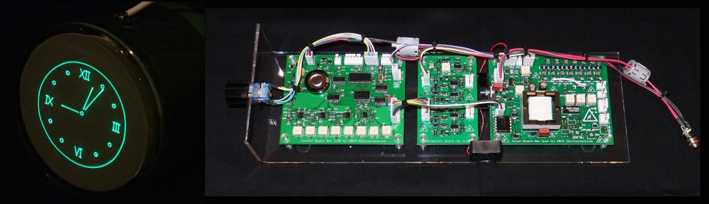
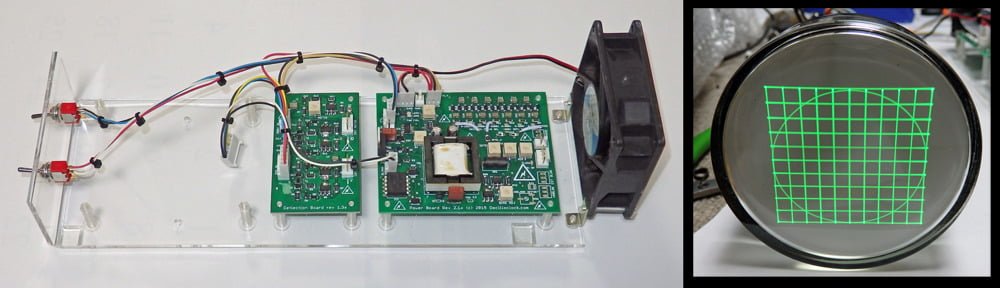
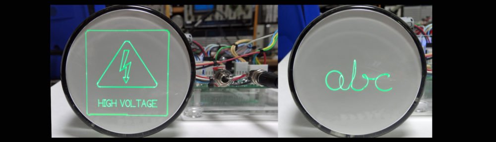
Here is the newly revamped Oscilloclock X-Y-Z Core, shipped out in Q2 2016:

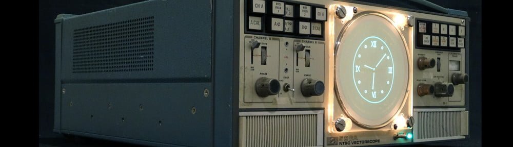
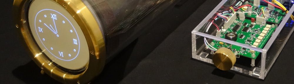
And here is what [Mike] was able to with it, after implementing a totally fresh controller design incorporating Circle Graphics:

Here is [Mike’s] story in his own words:
I was thinking of building a Nixie clock, but when I discovered the vector graphic clocks that Aaron and others had built, I knew I needed to build one. I felt comfortable that I could recreate my own version of the digital logic and the low-voltage analog signals, but didn’t really want to tackle the deflection amp or the high voltage circuitry. Buying the Oscilloclock XYZ display solved that problem. Everything arrived as and when promised, and I was beyond impressed by the care and workmanship that’s evident in everything from the boards to the harnesses to the documentation!
I based my controller board on a Cypress PSOC 5LP chip, which allows me to implement all of the digital logic in its on-board programmable logic fabric. The 80MHz 32 bit ARM processor allows me to program 100% in C, which enabled me to create my own version of the software fairly easily. (I tip my hat to those who have done it all in 8-bit assembly!)
Remaining work includes improving my signal quality, which doesn’t yet fully exploit the bandwidth and linearity of the Oscilloclock boards, designing an interesting enclosure, and adding a few software features.
Good luck [Mike] with the rest of your implementation!!!
Key features
This unit is the latest incarnation in a series started in 2015, for a client who needed a custom Head Up Display solution. The boards have undergone through several revisions since then to optimize performance. This particular kit was pre-configured and fully tested to support 3RPx, 3KPx and 3WPx CRT types, and features:
- Cathode to deflection voltage of 1875V
- Digital blanking (grid modulation), safely isolated at 2.2kV continuous working voltage
- Precision deflection amplifier capable of driving +/- 275V with 0.1% linearity
- 0-5V analog X and Y inputs with 2.5V reference output [Option RS]
- TTL/CMOS compatible high-frequency blanking input
- Dim/Bright digital input with PWM support
- Power Off digital input
- Temperature-controlled fan with Failure and Overtemp safety features
- CRT rotation coil supply (+/-5V)
- CRT heater soft start / inrush current limiting

Like what you see?
X-Y-Z displays are cool. But so are my other unique creations! See the Gallery, and stay tuned!