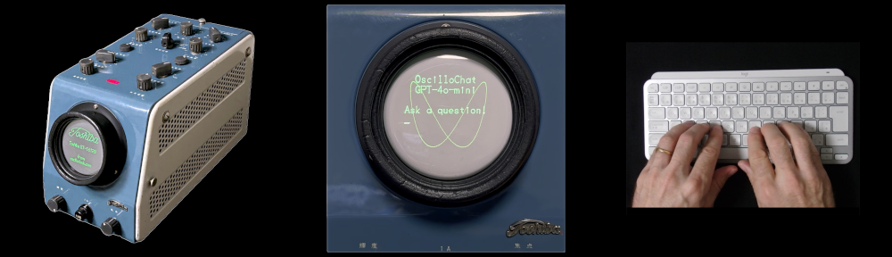
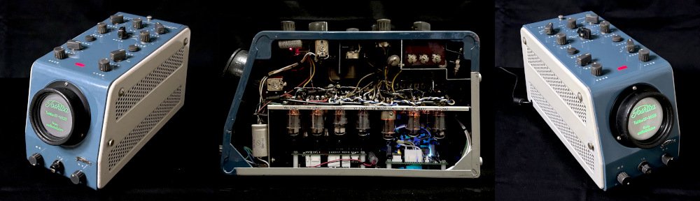
Author: Aaron

  • Oscilloclock Bare(ly) makes it to Brazil

    Whether directly or indirectly, the pandemic seems to have slowed everything down: chip production; the global economy; and even Oscilloclock blog post publishing!

    But perhaps most impacted of all is transport logistics. [Dante] in Brazil discovered this to his dismay in July 2020, when he purchased an Oscilloclock Bare unit. The P.O. had stopped all air service to Brazil just 3 weeks earlier – well after our discussions had started. Oh no!

    [Dante]’s crisp new Oscilloclock Bare, ready to go, but unable to ship!

    [Dante] waited patiently for 6 months for the post office to resume accepting airmail service to Brazil. But they never did. And FedEx and DHL came at too hefty a price. In desperation, he authorized shipment by sea – and at last, in December 2020, his package was off!

    Absence (of air mail service) makes the heart grow fonder...

    After an agonizingly long wait, [Dante] finally received his unit 6 months later – in July 2021. He then spent the next 5 months completing his dream project!

    [Dante]’s Dream: A Hewlett Packard retrofit

    The Oscilloclock Bare is designed to be a no-frills controller assembly that highly knowledgeable folks can install into their own displays. [Dante]’s dream was to use this to convert his beloved HP 182T / HP 8755C unit into a living, breathing scope clock.

    And convert he did!

    Question: How do you add ambience to a home?
    Answer: Instill new life into a device from yesteryear!

    Clearly, [Dante]’s 18 month end-to-end was worth the wait.

    The Build

    [Dante] was kind enough to supply a write-up of his project, including some clever solutions for pitfalls along the way. Let’s hear from him in (mostly) his own words!


    Motivation

    The model HP 182T is an oscilloscope featuring a large CRT with a graticule of 8 x 10 major divisions and a display area of 133 cm2, coated with a P39 aluminized phosphor for high brightness and long persistence.

    The HP 182T works as a display mainframe supporting other HP plug-in test equipment, such as the HP 8755C, a swept amplitude analyzer.

    Both items are nowadays considered “vintage” test equipment. But with the Oscilloclock board installed, they have been transformed into a unique appliance with a natural appeal for practical use. Far better than the regular surplus market destinations, or — even worse — destructive disposal!

    HP 182T + HP 8755C. Can you spot the Oscilloclock control board?
    Control board installed!

    HP 8755C in short

    This plug-in unit works primarily as a signal conditioner and a multiplexer for “almost dc levels” from three RF detector probes attached to three input independent channels. There are front panel adjustments for the scaling, gain and multiplexing controls that provide the appropriate Y-Axis composite signal for displaying by the HP 182T mainframe.

    The Oscilloclock control board was elected to be installed inside this plug-in unit.

    HP 182T in short

    This oscilloscope is built around the CRT with its high voltage power supply.

    The X-Axis signal from the Oscilloclock board is fed to the HP 182T’s chain of the horizontal pre-amp plus output amplifier, which drives the CRT horizontal deflection plates.

    The internal wiring of the HP 182T connects the CRT’s vertical deflection plates directly to the plug-in cabinet of the display mainframe, so the Y-Axis signal from the Oscilloclock board is routed inside the HP 8755C itself.

    The Z-Axis signal from the Oscilloclock board is fed to the HP 182T’s gate amplifier.

    Drawbacks

    Contrary to any standard X-Y scope where the two input channels are always supposed to have electrically similar (if not identical) characteristics, the correct operation of the Oscilloclock board for the application here was shown to be not as seamless as first imagined. You have to face some details of these integrated “host” equipment (HP 182T + HP 8755C) to see why…

    As described, there are distinct amplification chains accepting the Oscilloclock output signals. This presents specific challenges regarding (a) the differential gain for the X and Y signals, and (b) the differential time delay between any combination of the three X, Y, and Z signal outputs of the Oscilloclock board.

    First Approach

    Before having the board at hand and expecting to make it work as soon it arrived (the shipping took longer than expected due to COVID restrictions), I first planned the signal flow and did the wiring. I had one eye on achieving a ‘clean packaging’ of the board inside the HP 8755C, and the other on ensuring compatibility between the Oscilloclock’s X-Y-Z output signals and their respective chains planned in the host equipment, considering signal amplitude and required frequency response.

    The adaptations made at this time considered a minimally-invasive approach, where the criteria was to “make it simple”. This was limited to just opening or re-using connections and keeping the existing routing, in order to use the Oscilloclock’s X-Y-Z output signals in the most simplistic way possible.

    Another necessary one-time adaptation was for the board’s power supply, and integration of its PSON output signal with the equipment’s hardware. This part of the design was successfully kept to the end of the project without any further modification.

    First time installation of the oscilloclock board

    Upon arrival and a bench test of the Oscilloclock board with a scope, I immediately figured out that the amplitude levels for the X and Y output signals were lower than expected (maybe due to my misinterpretation of the specs). I did the gain compensation corrections again and went thru the complete installation of the board inside the host equipment, anxious to see it working.

    What a disappointment when instead, up came a completely distorted and elliptically shaped image, blurred with noise, and what looked like un-blanked retrace lines. Worse yet, mainly when alphabetic characters were displayed on the screen, none of the shapes were correctly formed.

    Of course, that was time for a break — and a complete review of the job and the work done so far!

    Chasing the problems

    The Lissajous figures generated by the Oscilloclock board use an approximately 40 KHz  sinusoidal signal, so I started to play with an external generator at the same frequency and amplitude for the X and Y signals (at about 1 Vpp) and trace it inside the HP 8755C and HP 182T.

    At this time, I’d already exercised the Z-axis waveform from the Oscilloclock board and the expected processing through the HP 182T. There was no evidence of problems with this Z-axis signal chain, and I achieved a measured propagation delay of around 50 nS.

    The minimalist approach mentioned earlier showed its consequences, when a propagation delay of an impressive 8 uS was measured at the vertical deflection plates, and  around 1.5 uS at the horizontal deflection plates! It was time again for another break, to elaborate a new routing scheme for the X and Y signals.

    Final Approach

    From the previous analysis, I ended up with two different and both very large propagation delays for each of the X and Y signals (as compared with the measured 50 nS for the Z-axis). How to solve this? It did not seem to be only a routing problem.

    I decided to investigate X-Y-Z signal propagation delays in the two units separately. After a thorough measurement of propagation delays inside the HP 182T itself, comparing with the HP 8755C plug-in itself (where the Oscilloclock board was installed), I concluded on two countermeasures:

    1. The complete removal of the Processor board XA-6 from the HP 8755C. (This is where the Y-axis signal from the Oscilloclock board had initially been connected.) Instead, this routing was transferred directly into the Normalizer Interface board XA-11 (which interfaces with the HP 182T).

    2. Also at the Normalizer Interface board XA-11 inside the HP 8755C, the substitution of two original op amps U9A and U9B (HP #1826-0092) by TL072 op amps, which are faster and have a higher slew rate.

    These solutions were enough to align the signal propagation and complete my project!

    Dante JS Conti, 8 November 2021

    Like what you see?

    We do! We love to hear back from Oscilloclock owners, to hear their stories.

    Check out our previous posts and the Gallery for info on other unique creations!

  • New Year’s Resolution!

    Q: “What’s your New Year’s Resolution?
    A: “Why, 1024 x 768, of course!”

    Geeky jokes aside, here at the Oscilloclock lab we DO have a form of New Year’s resolution! 「日進月歩Nisshin-geppo, which loosely translates as “Steady progress day by day“, reflects the goal to complete the the once-in-a-decade re-design work, and resume crafting beautiful Oscilloclock products. It also highlights confidence that issues currently facing the wider world will be overcome, one step at a time.

    In keeping with local traditions, [Oscilloboy] wrote the slogan in Japanese calligraphy. But there, tradition ended and true joy began! Behold, courtesy of an Oscilloclock VGA Core assembly, Oscilloclock’s 2021 New Year’s resolution on a beautiful old 7-inch oscilloscope!

    The Setup

    After choosing an appropriately meaningful four-character phrase for our resolution, I asked [Oscilloboy] to write out the characters. Bucking with tradition, we used standard white A4 paper instead of calligraphy paper. The ink took more time to dry, but we wanted to maximize the contrast.

    After scanning the handwritten characters and inverting the images, I created a rolling video in 1024 x 768 resolution. (See? The joke at the beginning of the post about resolution was serious, after all!)

    I then played this through an Oscilloclock VGA Core assembly, which is essentially a graphics card that allows you to use a beautiful old CRT as a rudimentary computer display. (For earlier write-ups, see VGA display… On a 3″ scope tube! and The VGA Cube! .

    The assembly used here features a late prototype of the Revision 3 Power Board, which I have been working on for almost a year. I won’t go into all the bells & whistles yet. Stay tuned!

    A VGA Core assembly – displays monochrome images from VGA, SVGA and XGA inputs

    Unlike a permanent Oscilloclock conversion (see the Gallery for examples), this was only a temporary setup. The VGA Core was positioned externally, with the harness routed into the 7VP1(F) CRT via the rear of one of the side panels. No invasive procedures needed!

    Just LOOK at that beautiful CRT socket – brown Bakelite!

    No VGA socket on your ultramodern slim notebook of choice? No problem – use an off-the-shelf HDMI to VGA converter!

    And voila – the final result! Japanese calligraphy on a vintage 7″ oscilloscope!


    About the Model – A rare 1963 Nitsuki Oscilloscope

    Nitsuki is the brand name of Japan Communication Equipment Co., Ltd., a specialist in television and microwave broadcasting systems. The firm’s English name was originally Nihon Tsushinki Co., Ltd., so you can see how the Nitsuki moniker came about.

    Check out this exquisite cap on the pilot lamp!

    By 1963, the Japan domestic test equipment market was mature and quite competitive. English language labeling had become stock-standard. This scope is one of very few units I have ever obtained that has Japanese labeling. How appropriate for today’s display!

    Japanese labeling – a rarity!

    Some of the higher-quality oscilloscopes of this era featured flip-latches and detachable side panels, for easy access. See the Toshiba ST-1248D for another example. These scopes are infinitely more enjoyable to work with and show off than scopes with a slide-out chassis.

    This model is also quite unusual for its time in that most of the components are located under the chassis! The valves (tubes, if you prefer) are even mounted horizontally. Nitsuki used very robust construction techniques, including very tidy cable lacing.

    In fact, their design was so robust that the scope functions almost perfectly today (except for some triggering instability), yet there is no evidence of major repairs in the last 57 years!

    Back to its natural self – a nice old 7-inch 1963 oscilloscope!

    Like what you see?

    The Oscilloclock lab struggled in 2020 due to worldly events, but NOW – day by day, step by step, the newly designed Oscilloclock boards are at last taking shape! Does your New Year’s ‘resolution’ for your next project specify 1024 x 768? Or perhaps you’re into displaying fancy calligraphy on vintage CRTs? Let me know.

    And as always, see previous posts and the Gallery for info on other unique creations!


    Critical Update 25 December 2021

    Well. Christmas Day 2021, and [Oscillowife] — the chief editor, advisor and critic extraordinaire — just informed me that I had placed [Oscilloboy]’s first character「upside down when creating this post! Apologies to our readers for the gross oversight.

    It’s been 12 months! But better late than never to eat humble pie…
  • For those cat lovers out there, let me present one beautiful kitten who knows his place in life: bedded down amongst some beautiful Brimar CRTs!

    Cathode-ray Cat

    This picture, submitted by an Oscilloclock aficionado, proves that there ARE others with an intense passion for CRTs out there. And this group now includes the feline species!

    Anyone out there have a capacity-controlled canine? An electron-excitable echidna? Or a filly with a phosphor fetish? Let me know!

  • Brimar Beauties for Plug & Play

    [Atif] is quite fond of his custom Oscilloclock Model 1, originally supplied with a bright green Brimar SE5F/P31 CRT. He just loves its crisp, clear trace! But wouldn’t it be great if he could plug-and-play a different CRT, to suit his mood of the day?

    [Atif]’s Oscilloclock Model 1 SE5F with P31 green phosphor… Could we change the mood?

    More specifically, could I create a second display unit (the acrylic tube on the left) using a CRT with a soft, long-persistence blue trace? And could he just swap the units around at will, without having to make any changes to the control unit?

    Absolutely! But to make the 2nd unit completely compatible for plug-and-play, we’d need the same SE5F type CRT, with a different phosphor. Looking at Brimar’s catalogue, this CRT was available in several phosphors – including a P7 blue. This is the same as used in the original Prototype, and it’s really good at showing off those exotic trailing effects!

    SE5F P7 specs

    So the hunt began…

    Now, this particular P7 CRT is famously difficult to come by – whether new OR used.

    The most common piece of old equipment employing the SE5F was the ubiquitous Telequipment S51 oscilloscope, but the overwhelming majority of those had a P31 phosphor CRT installed. Indeed, of all the demonstrably working S51’s posted on eBay in the past decade, I have never seen a single one showing an obviously blue trace!

    After many months of scouring auctions, suppliers and CRT fanatic colleagues across the globe, I managed to locate one SE5F/P7 in highly questionable condition – and located in Italy! With Google Translate as my friend, negotiations ensued, and – taking a substantial risk that the CRT would actually function – the unit was duly purchased and shipped.

    A dirty, slightly rusty SE5F/P7 CRT – snatched from the brinks of destruction in Italy

    Often, well-used CRTs exhibit scratches, spots, or burn-in marks on the internal phosphor coating. Fortunately, this CRT’s phosphor proved unblemished! And powering it up (for the first time in decades, most likely), it proved to be electrically faultless, as well!

    It works!

    Beautifying the Brimar

    You may think that cleaning a CRT is hardly worth writing home (or the world) about.

    Eucalyptus oil is amazing

    But this specimen was slathered in sticky, gooey tape residue, which had to be carefully removed. My chemical of choice for this is, believe it or not, eucalyptus oil! Not only does it remove the gunk, but it also serves to clear up any nasal or bronchial congestion that the technician may have at the time. Two birds with one stone!

    The more difficult issue was removal of the graphite coating. During manufacture, the front-most 8 cm of the glass of each SE5F was sprayed with a conductive graphite-based paint. Why? To make a high-voltage capacitor with the spiral accelerator anode (the beautiful green stripes) and similar graphite coating on the inside of the glass. By connecting the external coating to ground, the thrifty circuit designer could avoid using a separate (and expensive) high-voltage filter capacitor in the anode power supply!

    External and internal graphite coatings form an effective high-voltage capacitor!

    Why remove this coating? Because during use, it gets scratched and marred, as the above photo shows. Such a messy CRT could never be worthy to mount in a clear cast-acrylic case for an Oscilloclock! In addition, the coating obscures some of the attractive spiral accelerator anode, and blocks the incredible view of the trace from behind. And regarding circuit design, we at Oscilloclock NEVER scrimp – the Power Board has oodles of filtering capacity without relying on a graphite coating!

    While eucalyptus oil is also effective, it can get rather expensive in the quantity required – especially as the Oscilloclock lab is not conveniently located in Australia! The more reasonably priced chemical of choice here is nail polish remover. As always, there is a side-benefit – the nasal passages are assuaged by a delicate floral scent during cleaning, and fingers have an arguably nice smell that lingers for quite a while!

    Joking aside – gloves, open windows, good ventilation, and safety glasses (in case the CRT implodes) are key ingredients for this process!

    Eucalyptus oil and nail polish remover has done wonders to this Italian-sourced beauty!

    Onward!

    Having found the perfect CRT, [Atif]’s plug & play unit is now well under construction.


    Epilogue – “Good things come in threes”

    It’s not good just getting one CRT. What if [Atif] wanted a spare? What if I wanted a spare for my venerable Prototype clock? Following from the Italian success, I continued a further 6-month hunt, and managed two achievements.

    The first was a Telequipment S51b unit located in the U.K. that was non-functional, but that I suspected may have a P7 phosphor installed. How could I possibly suspect this? Well, perhaps this is an art rather than a science, but there were several tell-tale signs:

    • The way the phosphor looked under the camera flash or ambient light
    • The colour (or absence) of the graticule (the plastic cover in front of the CRT)
    • The fact that I got a double when I rolled the dice to decide whether to take the plunge or not!
    Oops, it was a P31 – the dice did not roll in my favour that time!

    The seller of this unit was not willing (or perhaps not technically able) to extract the CRT, check the CRT type, or ship overseas. Fortunately, my colleague in the U.K. was more than happy to receive the scope at his end. Thus arranged, when the unit arrived he extracted the CRT and confirmed that – sadly – I had purchased a P31 CRT.

    But I shipped it across anyway, and the CRT tested well. Rescuing a functional SE5F/P31 from eventual demise was still a worthy accomplishment!

    The second achievement was prompted by an auction listing for a “Brimar SE5F”, but with little indication as to the phosphor. The photos of the label (see right), even with subsequent close-ups provided by the seller upon request, were not conclusive.

    The image shows two characters beginning with ‘P’. It looks like “P1”, which is another extremely common green phosphor used in many CRTs since the beginning of time. However, we saw in the catalogue earlier that Brimar only supplied GV, P7, P31, and P39 phosphors as standard. It is unlikely that any equipment manufacturer would have requested Brimar to produce a custom CRT batch using the less-exotic P1 phosphor… Leaving the P7 as the only likely candidate!

    Convinced, the CRT was duly shipped across and tested – and lo and behold, success! A spare P7 was safely procured.

    And with that, the long saga of this CRT hunt closes. As they say, “good things come in threes!”


    Like what you see?

    Cathode ray tubes used to be manufactured in all shapes, sizes, and colours. Some prove harder than others to find! But if you prefer an exotic creation, don’t give up – there is something for you out there, and here at Oscilloclock we will find it.

    As always, see previous posts and the Gallery for info on unique creations!

  • Recently I had an enquiry from [Frank], who had just begun a life-long love affair with scope clocks by purchasing one on eBay. The clock was great – but he felt that the two available screens (simple analogue and digital clock faces) lacked a certain oomph.

    He then stumbled across Oscilloclock.com, and in his smitten state immediately reached out with his number one question: just what screens are available on an Oscilloclock?

    Well, let me save Frank’s time trawling through years of blog posts. Right here in one place are most of the Oscilloclock screens and features created to date.

    Enjoy the show!

    Standard Time Screens

    These stock-standard analogue and digital time screens may be quite simple, but they do evoke the ‘retro’ look that most people appreciate.

    And you can flip a menu setting to display days, months, years in Japanese:

    There are also some ‘random’ screens that add in a bit of dynamic visual entertainment:

    • Random number screen
    • Random letter sequence screen
    • Random four letter word screen (clean words only, by default!)
    • Random phrase screen (the phrase list is typically customized to a theme)

    And of course the mesmerizing Timedrops screen:

    Themed Screens and Features

    … These themed features were developed more recently, and can be added for a small fee to help cover development costs!

    Astroclock (Sidereal Time)

    External XY input

    OscilloTerm (serial terminal)

    Oscilloblock (lego)

    Metropolis

    Aftershock Clock (Earthquake display)

    Unbirthday Clock

    War Games

    Logo screens

    Over the years many folks have requested that I render custom logos in Circle Graphics. Here are some examples:

    “Seasonal Treats”

    Up next are some fun, mildly interactive animation features. Not exactly screens per se, these animations pop up after a predefined period of inactivity – but only during certain months of the year. Can you guess which months?

    Boo!
    Santa in your Clock!

    Menu screens

    There are far too many configuration menu and test screens to present here. Fiddle to your heart’s content!


    Q. How are screens switched?

    Screens are switched simply by rotating the control knob in one direction or other.

    There is also a configurable auto-switch feature; the screen is changed every 90 seconds in a predefined order (with the exception of some animation screens). The display time is configurable, and the auto-switch feature can also be turned off for those who prefer to switch screens manually.

    Q. How are screens selected & configured?

    Customers can request screens to include and/or specify the switching order. The configuration is done here in the lab before clocks are delivered.

    Oscilloclock also provides a firmware upgrade kit, which allows the customer to upload a revised version of the firmware into the clock themselves. Using this, updates to screens and other features can be uploaded without shipping the clock back to the lab.

    Q. What is the process for rendering a custom screen or logo?

    We typically prepare a mock-up based on the customer’s description, sketch, or image file. This is tweaked as needed until the screen looks just right to the customer.


    Like what you see? Contact me!