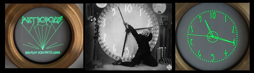
A few months ago, [Andrew] – of Metropolis Clock fame – reached out for help. He had just pulled his lovely Oscilloclocks out of storage to put on display, when he observed odd behaviour in both units: the time was accurate, but the date was stuck – to some random date back in 2003!
What on earth was going on?
What’s going on was not “on Earth” after all! [Andrew]’s clocks synchronise time and date against satellites, using an external Garmin GPS unit. And this unit happened to have a serious flaw. In this series of three articles, we’ll look closer at this accessory, identify this issue, and see how we were able to resolve it. Enjoy!
Our longevity dream
We want your Oscilloclock up and running as long as you are – and even beyond! Our dream is to see these beloved devices inherited by loved ones, and even available on the second-hand market as antiques one day.
In an era of throw-away technology, we flaunt an unthinkable target: Decades of trouble-free* operation.
* Excluding the CRT itself – although we really try hard with that as well, as this post explains!
To maximise usable lifetime (and safety!), we construct Oscilloclock units from the finest materials and components available. As part of this, we also select manufacturers that guarantee their components and provide decent after-sales support.
And Garmin is one such manufacturer…
Welcome to the Garmin GPS ‘Puck’
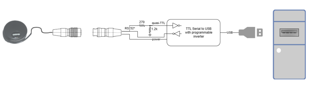
All Oscilloclock models that synchronise time using an external GPS unit have so far been supplied with a Garmin 18x LVC GPS unit, colloquially known as a ‘puck‘. (Note: to extend the lifetime of the pucks, we do not recommend using them on the hockey court.)

Now, this is not the smallest external GPS unit on the market today. But it has been available from Garmin since 2007, and is even being manufactured today! It is one of the most sensitive, robust, and well-supported units out there.
(Of course, for every new Oscilloclock delivered we evaluate afresh based on the latest devices available.)
This puck has a special connector …
How many times have you relegated an expensive laptop, phone, or other random device to the trash just because the power socket or headphone jack failed? Some of the weakest components of any electrical device are its connectors – plugs and sockets.
To combat such failures, your puck is wired with an exceptionally high quality connector from Hirose. This connectivity solution is not only robust, it even feels good! There’s a lovely audible and tactile ‘click’ when you engage the plug, and it locks securely in place. And unlike cheap chrome-plated connectors, we’ve proven that these babies do NOT corrode, even after a decade.


(more…)-- We don't scrimp - we only crimp!