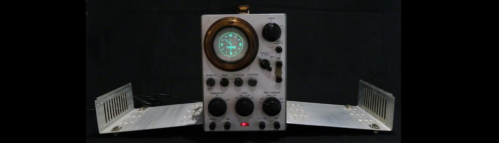
I believe in reincarnation. Every vintage device sporting a CRT deserves to live again, to be loved again, to lift someone’s spirits again. And in 2014, this beautiful Toshiba ST-1248D received its chance, born again as a suave Oscilloclock!
Manufactured sometime in the mid to late 1950’s, the ST-1248D was extremely well-designed and assembled, compared to other compact models available on the domestic Japanese market at that time. The engineers considered both function and form – latched panels on the side and back, delicately laced wiring, and a relatively spacious interior conducive to heat removal and circuit reliability. But the delightful brass bezel is what really makes this one of the most beautiful Oscilloclock conversions ever.
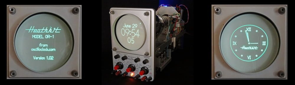
It seems that the Heathkit OR-1 is a very rare oscilloscope nowadays, and Chuck Penson reached out to me for a photo to put into his latest book, Heathkit Test Equipment Products. This is a very well-written, well-researched treasure trove of data about the most iconic kit manufacturer of its time. Highly recommended!
Chuck Penson’s latest book – superbly authoritative
Fresh from Oscilloclock Labs – a new VectorClock creation, commissioned for the office of a world-famous film and television director:
Tek 520 VectorClock – S/N 002 (image published with permission of the owner)
This unit is based on an original Tektronix 520 vectorscope, which is the predecessor of the 520A that was used in the first VectorClock, described here. This custom conversion employs several key enhancements, and performance has never been better!
What do you do on a mundane business trip to London?
Why, shopping, of course! But if you were the humble proprietor of Oscilloclock.com, you would do much more than that… You would seek to expand your vintage electronic empire!
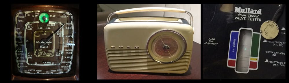
And so it was that I found myself hunting old electronic devices on Portobello Road one fine Saturday morning. Unfortunately, the game there was far and few between; only two relatively mediocre valve radios, in even more mediocre shape, at far more than mediocre prices…
Fortunately, my colleague was going to save the day. “Pop out to Cambridge for a visit – I’ve seen a few antique shops here,” said he. And after the hour train journey and a wee but of walking, we stumbled onto a veritable gold mine – Robbie’s.
Yes, you’ve all thrown away your lunky old CRT monitors, in favour of sleek ultra-thin LCD displays. And, you thought you’d never see another one again…
But this CRT display has a twist! It’s round. It’s small at just 3 inches diameter. And it’s awfully cute.
Last year, I was approached by a dedicated flight simulation enthusiast, who needed a radar indicator to use in a fighter cockpit replica. The indicator should employ a CRT, for the most realistic look. Could Oscilloclock design and construct such a display?
It didn’t take much convincing! Diverging only temporarily from building clocks, I took up the challenge to create my first raster-scan CRT display unit. In the ensuing months, difficulties sprang forth from every direction in the project, but ultimately I was able to avoid a diraster (sic) and deliver a functional assembly:
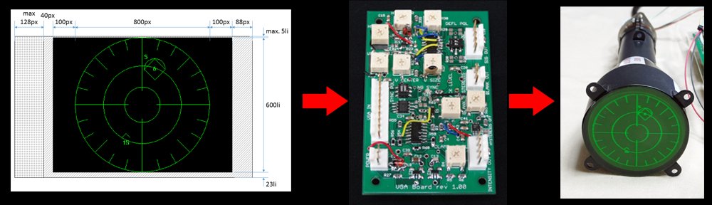
The key component of this setup is a new prototype VGA Board that converts a VGA signal into analogue X and Y outputs. Both analogue intensity and binary blanking outputs are provided.
Oscilloclock VGA Board prototype
The X and Y outputs drive an Oscilloclock Deflection Board, while the binary blanking output drives the blanking amplifier in a CRT Board. Blanking isolation, heater, and HV supplies are provided by a Power Board.
Deflection Board – modified for ultra-linear HV outputCRT Board – modified for improved frequency responsePower Board – with improved optocoupler
It all looks so easy! But noooo. Astute readers will recall from other posts that every Oscilloclock project involves sleepless slumbers, horrific hair-pulling, and forgotten family members. Let’s see what caused me grief this time…