In a desperate attempt to save his blog from becoming the all too familiar not-updated-in-5-years dead blog, the senior technician has resorted to seeking help from one of his sons, previously referred to as the 1st junior technician. Although my knowledge on CRTs and electronics is close to none compared to that of the senior technician, I will give you some updates on the recent activities of the main man himself, who I am sure all of you are eagerly awaiting the return of.
Amid the COVID-19 crisis, the senior technician has been lucky enough to be able to work at home. You would think that without his everyday commute of two hours, he would be more relaxed and able to spend more time with his family members. However, he is instead spending excessive time in front of the computer. At first, I speculated that he was having a rough time with his work. Or was he? Under closer examination, I realized that the additional time spent on the PC was actually something related to Oscilloclock. Something about a brand new design: “once-in-a-decade refresh,” and some such. Not really sure how significant this is to you all, but judging from the look on his face when he emerges from his room for dinner, it must be something BIG!
Another clue that the Oscilloclock Lab is heavily active is the vast array of international deliveries to our home in the past half year. Shipments from countries that you’ve never heard of, in all shapes and sizes, arriving so frequently that I can’t help feeling for the poor postman who has to carry these heavy objects up to our door. I must tell you, there is nothing worse than hearing the bell ring and rushing down to the door anticipating your own Amazon delivery of a new pair of shoes, and instead seeing a massive box from Montenegro containing who-knows-what-type-of-CRT.
The master craftsman’s work could very well be hindered by the noise from his two highly energised teenagers, [Oscillokid] and [Oscilloboy]. So how does he maintain concentration? The secret is a well-positioned cave. His workshop is intentionally situated at the very edge of the house. He simply closes the lone door to the shop, to avoid hearing a dinner-call or a request for more screen time from his Oscillosons. Until, of course, the commander-in-chief of the household raises her voice!
So there it is, a brief update on what’s going on and how the senior technician’s doing. Rest assured that he is working very hard on his projects, and has not in the least swayed from his passion; indeed, he is more immersed than ever. He will no doubt inform all of you anxious readers of his magnificent projects once they are ready for exposure. Until then, thanks for reading, and stay safe!
For those cat lovers out there, let me present one beautiful kitten who knows his place in life: bedded down amongst some beautiful Brimar CRTs!
This picture, submitted by an Oscilloclock aficionado, proves that there ARE others with an intense passion for CRTs out there. And this group now includes the feline species!
Anyone out there have a capacity-controlled canine? An electron-excitable echidna? Or a filly with a phosphor fetish? Let me know!
[Atif] is quite fond of his custom Oscilloclock Model 1, originally supplied with a bright green Brimar SE5F/P31 CRT. He just loves its crisp, clear trace! But wouldn’t it be great if he could plug-and-play a different CRT, to suit his mood of the day?
[Atif]’s Oscilloclock Model 1 SE5F with P31 green phosphor… Could we change the mood?
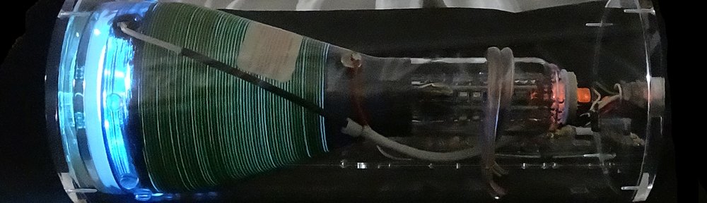
More specifically, could I create a second display unit (the acrylic tube on the left) using a CRT with a soft, long-persistence blue trace? And could he just swap the units around at will, without having to make any changes to the control unit?
Absolutely! But to make the 2nd unit completely compatible for plug-and-play, we’d need the same SE5F type CRT, with a different phosphor. Looking at Brimar’s catalogue, this CRT was available in several phosphors – including a P7 blue. This is the same as used in the original Prototype, and it’s really good at showing off those exotic trailing effects!
So the hunt began…
Now, this particular P7 CRT is famously difficult to come by – whether new OR used.
The most common piece of old equipment employing the SE5F was the ubiquitous Telequipment S51 oscilloscope, but the overwhelming majority of those had a P31 phosphor CRT installed. Indeed, of all the demonstrably working S51’s posted on eBay in the past decade, I have never seen a single one showing an obviously blue trace!
After many months of scouring auctions, suppliers and CRT fanatic colleagues across the globe, I managed to locate one SE5F/P7 in highly questionable condition – and located in Italy! With Google Translate as my friend, negotiations ensued, and – taking a substantial risk that the CRT would actually function – the unit was duly purchased and shipped.
A dirty, slightly rusty SE5F/P7 CRT – snatched from the brinks of destruction in Italy
Often, well-used CRTs exhibit scratches, spots, or burn-in marks on the internal phosphor coating. Fortunately, this CRT’s phosphor proved unblemished! And powering it up (for the first time in decades, most likely), it proved to be electrically faultless, as well!
It works!
Beautifying the Brimar
You may think that cleaning a CRT is hardly worth writing home (or the world) about.
Eucalyptus oil is amazing
But this specimen was slathered in sticky, gooey tape residue, which had to be carefully removed. My chemical of choice for this is, believe it or not, eucalyptus oil! Not only does it remove the gunk, but it also serves to clear up any nasal or bronchial congestion that the technician may have at the time. Two birds with one stone!
The more difficult issue was removal of the graphite coating. During manufacture, the front-most 8 cm of the glass of each SE5F was sprayed with a conductive graphite-based paint. Why? To make a high-voltage capacitor with the spiral accelerator anode (the beautiful green stripes) and similar graphite coating on the inside of the glass. By connecting the external coating to ground, the thrifty circuit designer could avoid using a separate (and expensive) high-voltage filter capacitor in the anode power supply!
External and internal graphite coatings form an effective high-voltage capacitor!
Why remove this coating? Because during use, it gets scratched and marred, as the above photo shows. Such a messy CRT could never be worthy to mount in a clear cast-acrylic case for an Oscilloclock! In addition, the coating obscures some of the attractive spiral accelerator anode, and blocks the incredible view of the trace from behind. And regarding circuit design, we at Oscilloclock NEVER scrimp – the Power Board has oodles of filtering capacity without relying on a graphite coating!
While eucalyptus oil is also effective, it can get rather expensive in the quantity required – especially as the Oscilloclock lab is not conveniently located in Australia! The more reasonably priced chemical of choice here is nail polish remover. As always, there is a side-benefit – the nasal passages are assuaged by a delicate floral scent during cleaning, and fingers have an arguably nice smell that lingers for quite a while!
Joking aside – gloves, open windows, good ventilation, and safety glasses (in case the CRT implodes) are key ingredients for this process!
Eucalyptus oil and nail polish remover has done wonders to this Italian-sourced beauty!
Onward!
Having found the perfect CRT, [Atif]’s plug & play unit is now well under construction.
Epilogue – “Good things come in threes”
It’s not good just getting one CRT. What if [Atif] wanted a spare? What if I wanted a spare for my venerable Prototype clock? Following from the Italian success, I continued a further 6-month hunt, and managed two achievements.
The first was a Telequipment S51b unit located in the U.K. that was non-functional, but that I suspected may have a P7 phosphor installed. How could I possibly suspect this? Well, perhaps this is an art rather than a science, but there were several tell-tale signs:
The way the phosphor looked under the camera flash or ambient light
The colour (or absence) of the graticule (the plastic cover in front of the CRT)
The fact that I got a double when I rolled the dice to decide whether to take the plunge or not!
Oops, it was a P31 – the dice did not roll in my favour that time!
The seller of this unit was not willing (or perhaps not technically able) to extract the CRT, check the CRT type, or ship overseas. Fortunately, my colleague in the U.K. was more than happy to receive the scope at his end. Thus arranged, when the unit arrived he extracted the CRT and confirmed that – sadly – I had purchased a P31 CRT.
But I shipped it across anyway, and the CRT tested well. Rescuing a functional SE5F/P31 from eventual demise was still a worthy accomplishment!
The second achievement was prompted by an auction listing for a “Brimar SE5F”, but with little indication as to the phosphor. The photos of the label (see right), even with subsequent close-ups provided by the seller upon request, were not conclusive.
The image shows two characters beginning with ‘P’. It looks like “P1”, which is another extremely common green phosphor used in many CRTs since the beginning of time. However, we saw in the catalogue earlier that Brimar only supplied GV, P7, P31, and P39 phosphors as standard. It is unlikely that any equipment manufacturer would have requested Brimar to produce a custom CRT batch using the less-exotic P1 phosphor… Leaving the P7 as the only likely candidate!
Convinced, the CRT was duly shipped across and tested – and lo and behold, success! A spare P7 was safely procured.
And with that, the long saga of this CRT hunt closes. As they say, “good things come in threes!”
Like what you see?
Cathode ray tubes used to be manufactured in all shapes, sizes, and colours. Some prove harder than others to find! But if you prefer an exotic creation, don’t give up – there is something for you out there, and here at Oscilloclock we will find it.
As always, see previous posts and the Gallery for info on unique creations!
Recently I had an enquiry from [Frank], who had just begun a life-long love affair with scope clocks by purchasing one on eBay. The clock was great – but he felt that the two available screens (simple analogue and digital clock faces) lacked a certain oomph.
He then stumbled across Oscilloclock.com, and in his smitten state immediately reached out with his number one question: just what screens are available on an Oscilloclock?
Well, let me save Frank’s time trawling through years of blog posts. Right here in one place are most of the Oscilloclock screens and features created to date.
Enjoy the show!
Standard Time Screens
These stock-standard analogue and digital time screens may be quite simple, but they do evoke the ‘retro’ look that most people appreciate.
And you can flip a menu setting to display days, months, years in Japanese:
There are also some ‘random’ screens that add in a bit of dynamic visual entertainment:
Random number screen
Random letter sequence screen
Random four letter word screen (clean words only, by default!)
Random phrase screen (the phrase list is typically customized to a theme)
Over the years many folks have requested that I render custom logos in Circle Graphics. Here are some examples:
“Seasonal Treats”
Up next are some fun, mildly interactive animation features. Not exactly screens per se, these animations pop up after a predefined period of inactivity – but only during certain months of the year. Can you guess which months?
There are far too many configuration menu and test screens to present here. Fiddle to your heart’s content!
Q. How are screens switched?
Screens are switched simply by rotating the control knob in one direction or other.
There is also a configurable auto-switch feature; the screen is changed every 90 seconds in a predefined order (with the exception of some animation screens). The display time is configurable, and the auto-switch feature can also be turned off for those who prefer to switch screens manually.
Q. How are screens selected & configured?
Customers can request screens to include and/or specify the switching order. The configuration is done here in the lab before clocks are delivered.
Oscilloclock also provides a firmware upgrade kit, which allows the customer to upload a revised version of the firmware into the clock themselves. Using this, updates to screens and other features can be uploaded without shipping the clock back to the lab.
Q. What is the process for rendering a custom screen or logo?
We typically prepare a mock-up based on the customer’s description, sketch, or image file. This is tweaked as needed until the screen looks just right to the customer.
These days, just about everyone has an old oscilloscope lying around. You know, an old, dusty, derelict scope handed down from Grandpa (or Grandma). Well, [Paul] had something even better – an old Tektronix 602 X-Y Monitor! Could an Oscilloclock Control Board drive this vintage beauty? Absolutely. Could I make an aesthetically pleasing case? Definitely. How about time sync via WiFi? Stock standard!
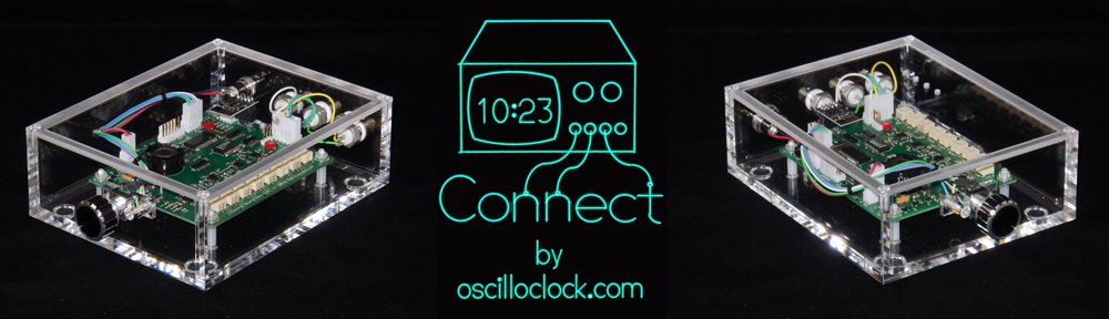
Presenting the Oscilloclock Connect:
Here’s what it looks like plugged in to my fabulous old Tektronix 620 monitor:
And why not have a pair of Connects drive a Tek 601 and 602?
The Build
The main component of the Connect is, of course, a standard Oscilloclock Control Board. As usual, all 121 parts on Paul’s board were individually mounted and soldered by hand. The board then was programmed and underwent rigorous inspection and testing. Finally, the board was cleaned to remove flux and renegade flecks of solder, and sprayed with HV coating for humidity protection and – arguably more importantly – to give it its glorious sheen.
The case was custom-made and professionally machined right here in Japan from 6mm-thick sheets of pure cast acrylic (not extruded). This is an extremely transparent, hard, high grade acrylic – and Oscilloclocks deserve nothing less!
The case was sprayed with a special acrylic cleaner and static protection solution, before fitting the various components. Naturally, every part was cherry-picked, right down to the three BNC connectors – they needed an aesthetically pleasing colour, but they also had to have a shaft long enough to mount through 6mm-thick acrylic!
Finally, the physical interface! The knob was chosen for its perfect finger-fit and delicate aluminium/black tones, which gently contrast with the rest of the unit.
The Compatibility Crisis
Over the years, many folks have observed that the scope at hand has an “X-Y mode”, and asked if they could just ‘plug in’ an Oscilloclock Control Board. “Is it compatible?” Unfortunately, the response has usually been disappointing.
You see, creating figures and characters with Circle Graphics relies on the scope’s ability to turn the beam on and off at split-second intervals. This feature is called a “Z-axis input”. While many scopes from the 80’s and beyond do sport such an input, there are two common limitations:
Limitation 1: AC-coupled Z-axis inputs
Capacitive coupling – effective at isolating the input from cathode potential (-1260V !)
The input is connected to the CRT’s grid or cathode circuit via a capacitor. This is a low-cost, effective way to isolate the (usually) very high negative voltage of the grid circuit from the input.
The problem here is that the capacitor, by its very nature, removes the edges from the pulse. The controller is no longer able to control the beam on/off timing, and you end up with uneven blanking across the segments, as shown in the screenshot at right.
Depending on the values of the capacitor and the surrounding resistors, the symptoms may not be severe. However, the best way to resolve this problem (while still keeping the oscilloscope’s original circuit intact) is to insert an isolated DC blanking amplifier directly in series with the grid (or cathode). See the Kikusui 537 Oscilloclock for an example of this.
LIMITATION 2: INSUFFICIENT BLANKING AMPLIFICATION
Most oscilloscopes tend to require at least +5V on the Z-axis input to noticeably blank the beam. The Connect, however, is only capable of delivering +2.5V. It works just fine if you set the scope’s Intensity control very low, but as you increase intensity, the blanking quickly becomes ineffective.
Below we have a beautiful Japanese YEW (Yokogawa Electric Works) 3667 storage scope. The left shot is misleading due to the camera exposure; the displayed image is actually extremely dim. The right shot shows the same* image with the intensity control increased – the image is bright, but there is no blanking!
* Astute readers will observe that the time is significantly different between the two shots. This is a result of the WiFi NTP sync kicking in right in the middle! More (or less) astute readers may also notice that the scope’s trace rotation is not adjusted very well…
Of course, it would be a simple matter to incorporate a pre-amplifier for the Z-axis, which would solve this problem. This will be introduced with the next Control Board revision!
Like what you see?
Nothing brings more joy than connecting this bundle of usefulness into a woefully unused old oscilloscope or X-Y monitor. If this is of interest to you, visit the Availability page for more information, and of course see the Gallery for other unique creations!