Humpty Dumpty sat on a wall…
Humpty Dumpty had a great fall…
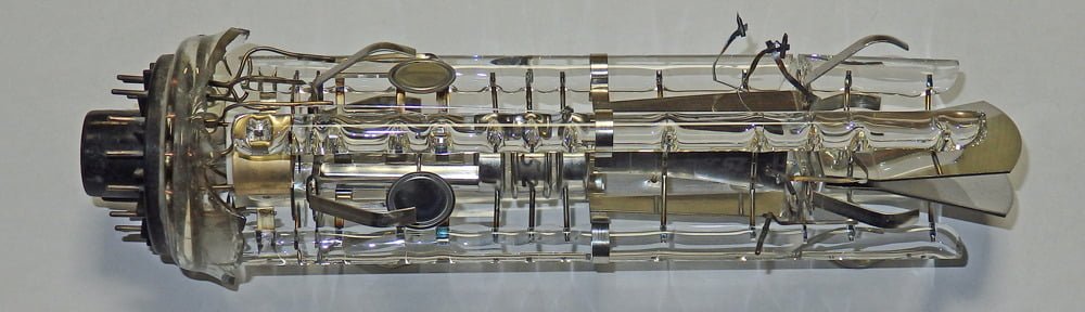
…and so the great nursery rhyme goes! But here at Oscilloclock labs, we’re not talking about an egg (which, one theory goes, represented the defeated King Richard III). We’re talking about a beautiful old CRT, savagely shaken and shattered during international shipping. What a waste. But oh, what a great chance to see the insides close-up!