Diverging from CRTs only briefly but holding steadfast to the warm, soft glow of valves, here I introduce a piece of Valve Art crafted long before Oscilloclock came into existence!
I spotted this vintage 1967 ultrasonic cleaner unit at the local Ham Fair, and it was love at first sight. Originally with a steel cabinet with peeling paint, the unit wasn’t much to look at on the outside. But after applying a copper coat to the chassis and fitting a sleek acrylic cabinet, this device simply dazzles!
Featuring not one, but two of these stunning Hitachi 3T12 transmitting valves!
Who needs a heater in winter, when you can have one of these power-hungry devices?
I bet this lovely triode, with its zirconium-plated anode and thorium-tungsten filament, really impressed the original owner of this ultrasonic cleaner…
These aesthetic innards simply ooze awesomeness. It’s as if they actually designed this for the art museum!Made in 1967, but boasting an incredible 200W output – absolutely deadly !
Sadly, my workshop no longer had room for this historic showpiece, so with a heavy heart, I recently powered it down for the last time. However it will go to a loving new home…
As I’ve hinted before, your friendly Oscilloclock gang is entirely pacifistic. We abhor the thought of actual military activity in this modern day and age. BUT we love games just as much as anyone – and we also love light-hearted movies with happy endings!
So when [Ian] (of Bunker Club Clock fame) came up with the idea of a feature based on the iconic 1984 flick “War Games“, I pounced on the chance!
Now, this may look like a simple animation. But Ian’s Oscilloclock is powered by a tiny processor with minimal specifications, and 100% of the code is written in assembly language. Implementing this baby in assembly and keeping within just 3K of RAM was quite an accomplishment!!
About the host clock
The gorgeous model shown here is a painstakingly-retrofitted Heathkit CO-1015 Engine Analyzer. It’s the perfect play-toy for any serious motor-head who grew up during the Cold War!
First up on the custom build list is the original meter fitted with amber LED lighting and ticking audibly each second. (And yes, the tick intensity can be easily adjusted.)
Next up, there is the optional External X-Y input feature. Normally, this is used for plain and simple Lissajous figures like the below…
… but by tweaking some settings, we can get some segments of Jerobeam Fenderson’s incredible Oscilloscope Music Kickstarter video to display quite nicely!
Peeking inside the Engine Analyzer Oscilloclock is also a must-do! Not only is this visually appealing, but you also get a significant olfactory kick from the sweet smell of vintage electronic components…
Attractive Oscilloclock boards and cabling, neatly tucked awayThe original circuit is completely bypassed – but still looks awesome!
Tech Talk – Strategies, Maps, and Missiles
The War Games feature uses the Oscilloclock’s Sprite Engine module to display the world map and up to 9 missiles when the W.O.P.R. system is simulating various war strategies.
32 of the 130+ strategies seen in the movie are implemented. For each strategy, a random number of missiles are launched along a predefined Primary trajectory, followed by a random number of missiles along a predefined Retaliatory trajectory. If any of the 9 missiles remain, they are launched along randomly selected (but predefined) trajectories.
Trajectories are predefined because computing them using 8-bit arithmetic would consume a huge number of cycles! At least, a small amount of randomness is added to the launch position and velocity parameters at run-time, to make things more interesting.
As the simulation progresses through the strategies, the speed of the launches increases and the delay between launches decreases. This gives a similar effect to that in the move, where WOPR moves through strategies at warp speed until it realises that there is no winning this game…
A Joint Effort
Creating a huge number of realistic trajectories (68 in total), translating start and end X and Y coordinates from latitude and longitude into the Oscilloclock’s Cartesian plane was a task of mind-blowing proportions! Here we see our 2nd junior technician eagerly earning his room and board.
Like what you see?
Are you a petrol-head? You need an Engine Analyzer ticking over at your bedside or in your office! Were you brought up during the Cold War, perhaps in the Soviet Union or in the US? Get the War Games feature and fry the world safely! Contact me if you like what you see.
(Disclaimer: Oscilloclock.com hopes that no-one is offended by the deliberately light-hearted tone of this post, in referring to the decidedly serious topic of nuclear warfare.)
When I first heard from [Masahalu], a local artist and woodwork craftsman, I had a hunch that Oscilloclock history was about to be made.
His request initially seemed simple; he wanted an Oscilloclock Core – a bare-bones board and CRT assembly, which he could install into a case of his own design.
However, he wanted something totally unique. Something old, yes, but also something new. The artist in him demanded a different canvas of creativity.
Presenting Masahalu’s new canvas: A 5″ amber CRT Oscilloclock!
Masahalu insisted on an “autographed” splash screen!More Oscilloclock Core: boards, cabling, WiFi module, power pack
Phantastic Phosphors
The new-old-stock CRT shipped with this unit features a P12 phosphor, and was originally produced for use in radar equipment. The phosphor’s long after-trace (persistence) allows for some fascinating ‘trailing effects’ in the Oscilloclock’s various animations.
Those familiar with CRT phosphors may point out that P12 is often classified as an orange phosphor, not “amber”. To my eye, though, the soft, warm trace of this CRT is better associated with eons-old fossilized tree resin than the sharp, bright color of fruit.
Amber? Or Orange? Depends on your point of view – and perhaps the camera!
Amber CRTs are quite rare, especially in larger sizes. 3-inch P12 CRTs can be found, but the Oscilloclock Lab was fortunate to find several of these rare 5-inch CRTs.
[Masahalu] has certainly ended up with the unique canvas he requested, and we look forward to seeing what kind of case design he ends up with!
Like what you see?
It’s so much fun letting these cathode ray tubes shine their colourful rays again! Whether you’re into yellow, amber, blue, white, or just plain green, there is something here for you. Visit the Availability page for more information, and of course see the Gallery for other unique creations!
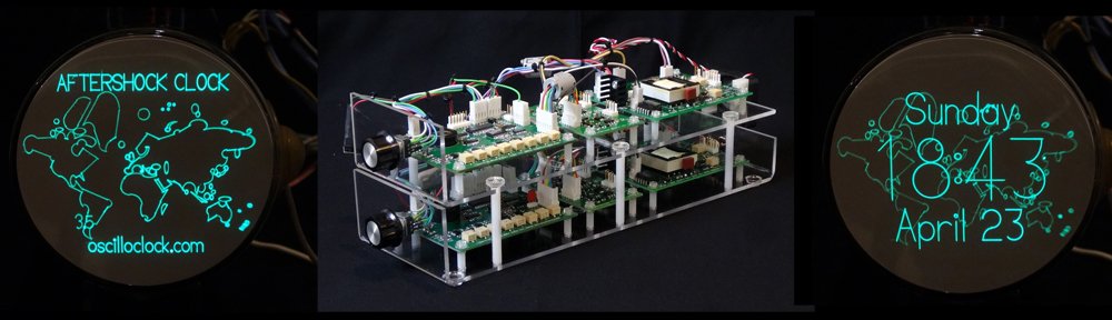
Fake news – a common keyword these days. Fortunately, Oscilloclocks do not display fake news. But wouldn’t it be handy to see quake news on an exotic scope clock? This is the challenge [Atif] gave me – and one year and many grey hairs later, here is the result: The AfterShock Clock!
This custom-crafted Oscilloclock Core Duo assembly is a unique first in several ways:
It’s the first scope clock ever that pulls in and displays real earthquake data!
It’s the first scope clock ever that puts a dual-beam CRT to good use – one beam for the clock display, and the other for the earthquake and map overlay!
Earthquake display
The AfterShock Clock’s WiFi module connects at regular intervals to two public APIs (servers) to collect the latest earthquake events. It then feeds earthquakes to the clock’s quake gun controller, rotating quakes every 30 seconds. Cool!
(Note: flickering is due to camera effects and is not visible to the human eye)
Of course, there is the usual wide variety of standard clock screens to cycle through! The quake map’s beam is automatically dimmed for most of the screens, giving a soft ‘watermark’ effect.
Dual-beam CRT
The E10-12GH CRT used in this clock is certainly not mundane!
Beautiful spiral PDA lets you really see inside the cavity!Nothing beats a dual-gun CRT for intricacy… (except a quad- or pentuple-gun CRT!)
Oscilloclock Core Duo
Atif wanted to create his own case, so he initially asked for an Oscilloclock Core. But currently a single Core set does not provide control, deflection, and blanking circuits to drive TWO electron guns… So he had two choices:
Wait an eternity for me to redesign the boards to fully support dual beams.
Get started now! Simply put two Core assemblies together, with some degree of inter-control and removing any redundant circuits.
Atif chose the latter – and the Oscilloclock Core Duo was born!
WiFi setup
Setting up the WiFi connection is easy – just connect a device to the clock’s administration SSID and pull up the admin page. (To foil any would-be hackers out there, the admin SSID is available only for the first 5 minutes after power is applied.)
Then, access the admin URL and configure the connection to your home router:
There are a million other advanced settings to tweak things such as quake polling interval, quake magnitude filters, maximum quake age before purge, and other geeky aspects…. See the Support page.
Oh, I forgot to mention – the clock also synchronizes time against an NTP server, eliminating the need for a GPS module.
Like what you see?
Do you go for electron guns? idolize intricate electrode assemblies? Have a filament fetish? Or just want some quake news? This kind of clock might fit the bill. Let me know!
Some readers may be curious just where these crazy Oscilloclock devices are actually made. While the question of WHO makes them shall remain a mystery, let’s definitely take a close look through the mad scientist’s laboratory!
This panoramic view of the depths of the shop makes the place look huge, but in fact it is a tiny 8.2 square metres (88 square feet)!
The entire workshop “sits” on the floor and is self-supporting – almost nothing is screwed in to the walls.
Perhaps the kind reader might think this is the production of a master woodworker. In fact, nothing could be further from the truth! This was the very first piece of furniture I have ever built – and as you can see, it was quite a project…
Design
First and foremost, I used SketchUp to create an accurate scale model of the workshop. I modelled every piece of equipment I wished to eventually mount, and tested hundreds of layouts until coming to a final design. What an effort!
Here I’ve loaded it into an STL viewer so you can play with it:
Woodwork
Most of the workshop is made from pine. All pieces of wood were cut from slabs using a cheap and nasty hand-held circular saw, as I did not have easy access to a table saw at the time. This was painstaking!
The workbench surfaces are solid maple for hardness and longevity. Linseed oil was used as a finish, to keep things natural. Unfortunately, I have been rather lazy and have neglected to apply further coats since making the workshop!
Maple, Pine, and lots of linseed oil!
Drawers under the benches were crafted carefully to allow resident Oscilloclock artists to sit with plenty of leg room, and drawer slides were chosen with appropriate length such that the drawers open out far enough to access fully.
Cabinets were fitted with adjustable internal shelving, and lovely hinges that allow access to the full width of the shelf even when the door is only open 90 degrees.
Shelves were fitted above windows on one side of the room, mostly to store my extensive collection of 1940’s to 80’s Australian electronics magazines (Radio and Hobbies, Radio Television & Hobbies, and Electronics Australia). These shelves are the only pieces in the workshop that are actually screwed into the walls.
For the reference bookshelf, I cheated and used a standard flexible solution from the local hardware store. It looks reasonable enough…
Electrical
The shop has its own electric meter, a second-hand one rescued from the junk pile. This one is designed for a much higher current than the humble Oscilloclock lab usually consumes, but it spins fast enough if I turn on enough equipment!
The shop is equipped with no fewer than five different power supply lines, all at the resident frequency of 50Hz:
100V – This may give away the lab’s country of residence…
100V isolated– For testing “hot chassis” devices
117V – Supplied by a massive, nasty 1500VA Variac
200V – Straight from the local power company
240V – Supplied by a massive hand-wound toroidal transformer
Earthed 100V, 117V, and 240V outlets are literally peppered around the workshop, mostly tucked away behind the shelves. Datacentre grade outlet boxes were employed for ultimate safety. The best part? All equipment is plugged in and ready to use at any instant in time!
Of course I also have a variable voltage, variable frequency AC power supply, which I use regularly when spinning up voltage into vintage gear, or when I need to evaluate power circuit performance at anywhere between 40 and 400Hz.
No shop should be without its own set of circuit breakers! Here we see two of the several dedicated switches. These employ earth leakage detection, of course.
Equipment
A quick flick through the Oscilloclock blog reveals beyond any doubt that I have an extreme passion for vintage electronics. Nowhere is this more visually expressed than in this homey workshop. Every piece of equipment functions, and every piece is actually used at least once a year!
But I shall leave the equipment show-and-tell for another post!
But WHY?
Well, for the fun of course! But in fact, this workshop was built exclusively for the design and construction of exquisite hand-crafted scope clocks. So don’t delay in checking out the fruits of the lab – visit the Gallery right now!