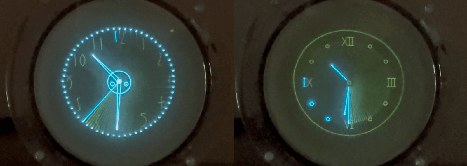
Amber Ambience

Amber.
Gentle. Soft. Warm.

New tech meets old tech – again.

When I first heard from [Masahalu], a local artist and woodwork craftsman, I had a hunch that Oscilloclock history was about to be made.

His request initially seemed simple; he wanted an Oscilloclock Core – a bare-bones board and CRT assembly, which he could install into a case of his own design.

However, he wanted something totally unique. Something old, yes, but also something new. The artist in him demanded a different canvas of creativity.

Presenting Masahalu’s new canvas: A 5″ amber CRT Oscilloclock!

Masahalu insisted on an “autographed” splash screen!
More Oscilloclock Core: boards, cabling, WiFi module, power pack

Phantastic Phosphors

The new-old-stock CRT shipped with this unit features a P12 phosphor, and was originally produced for use in radar equipment. The phosphor’s long after-trace (persistence) allows for some fascinating ‘trailing effects’ in the Oscilloclock’s various animations.

Those familiar with CRT phosphors may point out that P12 is often classified as an orange phosphor, not “amber”. To my eye, though, the soft, warm trace of this CRT is better associated with eons-old fossilized tree resin than the sharp, bright color of fruit.

Amber? Or Orange? Depends on your point of view – and perhaps the camera!

Amber CRTs are quite rare, especially in larger sizes. 3-inch P12 CRTs can be found, but the Oscilloclock Lab was fortunate to find several of these rare 5-inch CRTs.

[Masahalu] has certainly ended up with the unique canvas he requested, and we look forward to seeing what kind of case design he ends up with!


Like what you see?

It’s so much fun letting these cathode ray tubes shine their colourful rays again! Whether you’re into yellow, amber, blue, white, or just plain green, there is something here for you. Visit the Availability page for more information, and of course see the Gallery for other unique creations!

Quake News!

Fake news – a common keyword these days. Fortunately, Oscilloclocks do not display fake news. But wouldn’t it be handy to see quake news on an exotic scope clock? This is the challenge [Atif] gave me – and one year and many grey hairs later, here is the result: The AfterShock Clock!

This custom-crafted Oscilloclock Core Duo assembly is a unique first in several ways:

  1. It’s the first scope clock ever that pulls in and displays real earthquake data!
  2. It’s the first scope clock ever that puts a dual-beam CRT to good use – one beam for the clock display, and the other for the earthquake and map overlay!

Earthquake display

The AfterShock Clock’s WiFi module connects at regular intervals to two public APIs (servers) to collect the latest earthquake events. It then feeds earthquakes to the clock’s quake gun controller, rotating quakes every 30 seconds. Cool!

(Note: flickering is due to camera effects and is not visible to the human eye)

Of course, there is the usual wide variety of standard clock screens to cycle through! The quake map’s beam is automatically dimmed for most of the screens, giving a soft ‘watermark’ effect.

Dual-beam CRT

The E10-12GH CRT used in this clock is certainly not mundane!

Beautiful spiral PDA lets you really see inside the cavity!

Nothing beats a dual-gun CRT for intricacy… (except a quad- or pentuple-gun CRT!)

Oscilloclock Core Duo

Atif wanted to create his own case, so he initially asked for an Oscilloclock Core. But currently a single Core set does not provide control, deflection, and blanking circuits to drive TWO electron guns… So he had two choices:

  1. Wait an eternity for me to redesign the boards to fully support dual beams.
  2. Get started now! Simply put two Core assemblies together, with some degree of inter-control and removing any redundant circuits.

Atif chose the latter – and the Oscilloclock Core Duo was born!

WiFi setup

Setting up the WiFi connection is easy – just connect a device to the clock’s administration SSID and pull up the admin page. (To foil any would-be hackers out there, the admin SSID is available only for the first 5 minutes after power is applied.)

Then, access the admin URL and configure the connection to your home router:

There are a million other advanced settings to tweak things such as quake polling interval, quake magnitude filters, maximum quake age before purge, and other geeky aspects….

Oh, I forgot to mention – the clock also synchronizes time against an NTP server, eliminating the need for a GPS module.


Like what you see?

Do you go for electron guns? idolize intricate electrode assemblies? Have a filament fetish? Or just want some quake news? This kind of clock might fit the bill. Let me know!

The Oscilloclock Lab

Some readers may be curious just where these crazy Oscilloclock devices are actually made. While the question of WHO makes them shall remain a mystery, let’s definitely take a close look through the mad scientist’s laboratory!

This panoramic view of the depths of the shop makes the place look huge, but in fact it is a tiny 8.2 square metres (88 square feet)!

The entire workshop “sits” on the floor and is self-supporting – almost nothing is screwed in to the walls.

Perhaps the kind reader might think this is the production of a master woodworker. In fact, nothing could be further from the truth! This was the very first piece of furniture I have ever built – and as you can see, it was quite a project…

Design

First and foremost, I used SketchUp to create an accurate scale model of the workshop. I modelled every piece of equipment I wished to eventually mount, and tested hundreds of layouts until coming to a final design. What an effort!

Here I’ve loaded it into an STL viewer so you can play with it:

[stl file=”stl/Workshop.stl” stlviewer_fog_near=2000 stlviewer_fog_far=10000]
 

Woodwork

Most of the workshop is made from pine. All pieces of wood were cut from slabs using a cheap and nasty hand-held circular saw, as I did not have easy access to a table saw at the time. This was painstaking!

The workbench surfaces are solid maple for hardness and longevity. Linseed oil was used as a finish, to keep things natural. Unfortunately, I have been rather lazy and have neglected to apply further coats since making the workshop!

Maple, Pine, and lots of linseed oil!

Drawers under the benches were crafted carefully to allow resident Oscilloclock artists to sit with plenty of leg room, and drawer slides were chosen with appropriate length such that the drawers open out far enough to access fully.

Cabinets were fitted with adjustable internal shelving, and lovely hinges that allow access to the full width of the shelf even when the door is only open 90 degrees.

Shelves were fitted above windows on one side of the room, mostly to store my extensive collection of 1940’s to 80’s Australian electronics magazines (Radio and Hobbies, Radio Television & Hobbies, and Electronics Australia). These shelves are the only pieces in the workshop that are actually screwed into the walls.

For the reference bookshelf, I cheated and used a standard flexible solution from the local hardware store. It looks reasonable enough…

Electrical

The shop has its own electric meter, a second-hand one rescued from the junk pile. This one is designed for a much higher current than the humble Oscilloclock lab usually consumes, but it spins fast enough if I turn on enough equipment!

The shop is equipped with no fewer than five different power supply lines, all at the resident frequency of 50Hz:

  • 100V – This may give away the lab’s country of residence…
  • 100V isolated – For testing “hot chassis” devices
  • 117V – Supplied by a massive, nasty 1500VA Variac
  • 200V – Straight from the local power company
  • 240V – Supplied by a massive hand-wound toroidal transformer

Earthed 100V, 117V, and 240V outlets are literally peppered around the workshop, mostly tucked away behind the shelves. Datacentre grade outlet boxes were employed for ultimate safety. The best part? All equipment is plugged in and ready to use at any instant in time!

Of course I also have a variable voltage, variable frequency AC power supply, which I use regularly when spinning up voltage into vintage gear, or when I need to evaluate power circuit performance at anywhere between 40 and 400Hz.

No shop should be without its own set of circuit breakers! Here we see two of the several dedicated switches. These employ earth leakage detection, of course.

Equipment

A quick flick through the Oscilloclock blog reveals beyond any doubt that I have an extreme passion for vintage electronics. Nowhere is this more visually expressed than in this homey workshop. Every piece of equipment functions, and every piece is actually used at least once a year!

But I shall leave the equipment show-and-tell for another post!


But WHY?

Well, for the fun of course! But in fact, this workshop was built exclusively for the design and construction of exquisite hand-crafted scope clocks. So don’t delay in checking out the fruits of the lab – visit the Gallery right now!

Bunker Club Clock

It’s the 1970’s. The cold war. The U.S. and Russia aim nuclear weapons at each other. How do you prepare for the worst? Why, you build a bunker, of course!

Today, [Ian] has done just that. Not a real nuclear fallout shelter, of course, but a period-themed bar called the Bunker Club. What better way to face disaster, than over drinks with the mates!

Ian decided to pepper his bar with vintage equipment that looked the part. But he wanted to make them truly functional, to entertain his retro-loving customers. So, he commissioned the Bunker Club VectorClock!

Now, regular followers of the blog will easily recognize the base unit here as a Tektronix 520A Vectorscope. So far a total of four of these delightfully-lighted machines have been converted to retro Oscilloclocks – see the Gallery for other examples.

But as always with any model, Ian wanted to make some cool customizations. Let’s look at two of them.

1. External XY Input

First introduced in the Metropolis Clock, this feature allows Ian to input two signals and visualize them in X-Y format on the screen. This is very, very useful for generating custom Lissajous figures externally – using either a cheap signal generator, or even an iPhone!

Lissajous figures from an iPhone!

Cool Lissajous figures – even from a humble iPhone! (note, this picture is of the Metropolis Clock)

The external signals are rendered within a rectangular ‘window’, pre-configured to look nice alongside other standard parts of the Oscilloclock screens. For some screens, the window is drawn large but with a lower intensity, forming a kind of ‘watermark’. This is an awesome effect!

2. Custom Logos

Nearly all Oscilloclocks feature some kind of customized logo. Past examples include the customers’ business’ name, the name of the oscilloscope manufacturer, or even the name of the customer’s favourite film:

Toshiba ST-1248D - Brass bezel

Kikusui 537

Metropolis Clock

In Ian’s case, the obvious candidate was his new bar’s official logo – a very chunky-looking rocket blasting through the atmosphere!

Further enhancements … on the way

It seems Ian enjoyed his first clock so much, that he has commissioned a second, with a completely different physical look. Some further special effects and display animation are planned, to further enhance the nuclear theme and keep his customers happy. Stay tuned!


Like what you see?

Do you own a bar? Well, normally you wouldn’t want a clock in your premises, as it would help customers keep track of their time, which would be bad for business. But Oscilloclocks are so much more than timekeepers! Recent feature additions make them lots of fun to watch and fiddle with. If you have special ideas, let me know!

(Disclaimer: Oscilloclock.com hopes that no-one is offended by the deliberately light-hearted tone of this post, in referring to the decidedly serious topic of nuclear warfare.)

Improper Prop!

Veering slightly off the subject of the CRT and onto its cousin, the illustrious Magic Eye tube – it’s been a couple years since I wrote about the fortuitous visit to Robbie’s Place, where I picked up a beautiful Westminster ZA 617.

Not a CRT, but it’s lesser cousin – a soothing Y63 magic eye valve

Recently I was watching an episode of the British-Irish crime drama Quirke. Imagine my surprise when I spotted a ZA 617 in one of the scenes!

The fascinating thing was that this particular scene was set in a convent in the United States. But this radio was likely never sold in America! First and foremost, the radio doesn’t support 120V operation. Second, the dial markings, barely visible in the blurry close-up, reflect European radio station frequencies of of the time. Also, Long Wave was not particularly popular for public transmissions in the U.S. (as far as I know).

While it’s a clear case of an improper prop, the BBC had exceedingly good taste to choose this beautiful radio for the show. Long live magic eyes!

The VGA Cube!

It’s been a long while since I wrote about the 3″ VGA Display assembly, which was used for an RWR indicator in a fighter cockpit simulator.

The customer came back and requested four more. But could I stack the boards to make the units more compact? Of course!!

This particular assembly is rather tall because the client requested an in-built mains supply board, sitting at the bottom. The normal configuration using an external power pack is half the height. (In which case it’s not quite a “cube”…)

With green filter and replica RWR escutcheon fabricated by the customer. How real is that!!

And if you aren’t into aircraft indicators, you could always have a bit of fun!

Is a VGA Cube right for you?

Maybe. Or maybe not! These units incorporate binary blanking – I.e. The beam is either on or off; no shades of grey. Hence any VGA image composed of thick line art like RWR will display well, but shaded or coloured displays such as an attitude / horizon indicator would not work so well.

Below is a Windows XP login screen… Not exactly a flattering image!!

VGA Board – better and better

The latest VGA Board rev 1.1x is small and cute, and is compatible with the standard Oscilloclock Deflection and Power Boards.

In keeping with tradition, the VGA Board employs entirely analogue techniques to generate the horizontal and vertical sweep, triggered by incoming sync pulses. A high-speed analogue comparator with adjustable levelling is used to convert analogue RGB into binary blanking. Naturally, inputs are ESD protected so you can’t easily blow the chips!

New VGA Board revision (left) – meaner and leaner!


Like what you see?

VGA Cubes are like any other Oscilloclock product – each unit is hand-crafted to order and fully tested so that I can optimise for the selected CRT and provide a decent satisfaction guarantee. To date I’ve made five – and always happy to discuss a sixth! If you have a passion for raster rendering, let me know!

Burn-in? Nope!

Many folks have asked whether screen burn-in, or phosphor burn, is not a problem. They are concerned by what was a frequent occurrence in the CRT monitors and oscilloscopes of yesteryear: a permanent scar prominently visible on the screen…

Phosphor burn – this old spectrum analyser looks ‘on’ even when it’s off!

To understand why this occurs, first think of an iron burn. If you deliver too much heat for too long into the same spot, your nice new Oscilloclock brand T-shirt will feature a prominent (and permanent) mark as shown below.

Iron burn – this shirt’s fibres have been literally scorched!

(I could push for another analogy, and describe livestock branding – but I think you get the message.)

In a CRT, a beam of fast-moving electrons bombards the phosphor coating on the screen to produce an image. If the beam is too intense, or it is allowed to trace the same route on the screen over a long period of time, the phosphor compound may degrade and lose its luminance. The end result is:

  • The screen won’t light up well in those spots any longer.
  • The damaged areas may appear dark even with the power off – a ‘ghost image’.

Interestingly, this damage does not actually shorten the working life of the CRT! (It does not affect the longevity of the heater, or the amount of gas permeating the vacuum.) However, it is certainly not attractive, and is most definitely NOT an effect you wish to observe on your fancy custom-crafted Oscilloclock…

Keeping the ghosts at bay

Happily, screen burn-in is not much a problem with the Oscilloclock. Let’s see why.

1. CRT selection

Some CRT types and brands are more susceptible to screen burn-in than others. There are a number of factors for this, and all of these are considered during CRT selection to minimize the risk of burn-in:

First, there is the phosphor compound used. Some phosphors, just by their chemical makeup, degrade faster than others. More significant, though, is the fact that some phosphors require more energy (electron beam intensity) to produce the same level of visible light output as others.

For example, a long-persistence blue P7 phosphor, such as used in the Model 1-S and the Prototype, is by its nature ‘darker’; it requires a higher beam intensity than the crisp green P1 or P31 phosphors used in many other models. The higher beam does make the P7 more vulnerable to burn-in.

Different phosphors need different intensities to appear ‘bright’ – so some will burn faster

Fortunately, the simple protection mechanisms in place in the Oscilloclock (we’ll get to these later) will avoid burn-in even on sensitive phosphors. The customer need not be concerned about this risk factor, and can select any of the available phosphors.

The second factor is the thickness of the phosphor coating. The thicker the phosphor, the less burn-in for the same beam intensity. Some CRTs are infamous for having ridiculously thin phosphor coatings, making them extremely susceptible to burn-in. Sadly, some CRTs that are most readily available today fall into this category, and their data sheets even specify an incredibly short maximum longevity of 1000 hours. That’s less than 2 months of continuous use!

Beware CRTs with short lifetime ratings – they may have ridiculously thin phosphors!

Most CRT manufacturers did not publish lifetime ratings, nor did they publish specifications of phosphor thickness. In the Oscilloclock lab, I rely mainly on my and others’ experiences with the manufacturer, and pick and choose only the highest-quality CRTs. Expensive – but definitely worth it!

The third factor is the use of any additional technology in the CRT that would allow for reduced beam intensities. The most common example is the aluminized screen, an additional coating on the rear of the phosphor. This coating reflects the light that would normally emanate from the phosphor towards the rear of the CRT, back into the phosphor (and the front of the screen). A much more efficient use of energy!

However, this technology was a later development, so many CRTs with an aluminized screen tend to be rectangular and have an in-built graticule. These may not be as visually pleasing in a standard Oscilloclock as non-aluminized CRTs.

2. Software (Firmware) protection mechanisms

Remember the phrase “screen saver”? In the pre-LCD monitor days, most computers employed some form of software that would stop the same image being displayed for too long, to avoid screen burn-in.

My favourite screensaver – Flying Toasters!
(Image used under Fair Use terms)

While there is nothing as fancy as flying toasters, the Oscilloclock has several mechanisms in place.

  1. Hourly XY Bump screen saver
    This feature simply shifts the image by a small amount in the X and Y directions every hour. The shift pattern repeats every 31 hours (a prime number), to ensure that every hour numeral will be placed in every screen position.

  2. Auto screen switch
    This feature simply cycles through the screens (clock faces) at regular intervals, configurable from 0 (off) to 90 seconds. This is by far the most commonly enabled feature, as it allows one to enjoy all the Oscilloclock screens without touching the control!

  3. Auto power off
    Strongly recommended by Oscilloclock labs, this feature simply turns the Oscilloclock off after a period of non-activity (not touching the control), configurable from 0 (off) to 90 minutes.

    This may sound counter-intuitive, but in practice, nearly all Oscilloclock owners are comfortable to turn their unit on just when they intend to enjoy it, and allow it to switch itself off. The exceptions are clocks that are permanent fixtures in offices and restaurants, in which case the owners manually turn their clocks on and off together with other appliances in the premises.

These features are of course highlighted in the Operation Guide that accompanies every Oscilloclock.

Summing it up

So there we have it – there’s not so much to be concerned about after all. While CRTs do have a delicate phosphor coating, by selecting a decent CRT in the first place and looking after it in use, the risk of screen burn-in is drastically reduced. In fact, in 7 years of constructing Oscilloclocks, as of today not a single unit has come back for a CRT replacement!

Metropolis Time

In an earlier rambling, I introduced the Metropolis Oscilloclock, themed after the classic 1927 science fiction movie. The clock seems to have garnered some attention, and thanks to the kind folks over at Hackaday, I now have two additional facts to relate:

  1. The “Maria” robot in Metropolis inspired the design for C-3PO in Star Wars!
  2. Some folks have considered the Workers’ clock to be Decimal !

The first point stands without dispute, but let’s take a closer look at this “Decimal” aspect, as I’d never considered it before.

Decimal Time vs. Metropolis Time

Below is what got folks interested – the 10 hour clock face. The Masters used this to dupe the Workers into believing they were working short shifts, when in fact they were slaving away for a full 12 hours. Ingenious!

But this is not Decimal Time, where time is divided into units that are purely decimally related. Yes, there are 10 hours on the face, but there are 20 hours per day, and 60 minutes to the hour. And, if you bother to count the dots around the edge, you can see there are 72 seconds per minute. None of these are decimally related.

Speaking of decimal time, I fondly remember a Metric Clock article in the April 1987 edition of Electronics Australia. Being but a wee lad at the time, I was gullible enough to believe that true Decimal Time was going to be introduced in Australia imminently. I ‘convinced’ my father (he led me on) that it was really happening, and I was just about to purchase the kit to build my own Metric Clock… when in the following month’s edition, the magazine came clean that it was actually an April Fool’s joke!

But enough fooling around – let’s now take a closer look at the Oscilloclock implementation of Metropolis Time…

Metropolis Time vs. Regular Time

The two clocks in Metropolis differ only in one way: the length of an ‘hour’. This is easy to grasp, since there are 20 hours per day in one, versus 24 hours per day in the other.

But from here, Metropolis messes with your mind! Below are some revelations that [Andrew] and I battled over numerous e-mails to come to terms with:

  • The hour hands on the 10h face and the 12h face must always be exactly aligned (they must go around at the same speed).
  • Since an M-time hour is 20% longer, the minute hand must go around slower.
  • To make the M-time minute hand go around slower, the second hand must also go around slower.

Even if this makes sense so far, the crunch comes when you think about how to implement it. If it were a physical clock, the tick speed could be slowed and the gears could be modified to make the seconds and minutes go slower but the hour hand itself move at the same speed. Easy!

But it’s not a physical clock, and in the current Control Board design, the tick speed is NOT readily adjustable as it is derived from the MCU clock, which all the critical display routines are optimised around. So essentially, the length of a second cannot be changed.

Without changing the length of a second, how can we make the minute hand go around 20% slower? Well, there are only two options:

  1. Have 72 seconds per minute, with 60 minutes per hour
  2. Have 60 seconds per minute, with 72 minutes per hour

We decided on the first option, and you can see from the video below that the second hand indeed moves through 360 degrees in 72 steps (actually half that, since there is a half-tick).

An interesting tweak here is the shape of the hands. Note that they have triangular outlines, to more accurately mimic the hands in the film. But computing the angles and projecting these outlined hands using Circle Graphics was a true challenge – especially as the current Oscilloclock firmware is written 100% in PIC18F assembly code! Assembly is great for optimizing timing, but with no maths related processor instructions or functions to leverage, this feature was a huge effort…

Why assembly code? Just because I can!

Digital Metropolis Time

Everything was now all fine and dandy for the analogue 10h clock face, but what about all those nice digital faces that are stock standard in every Oscilloclock? Could I make Metropolis Time make sense in a digital format as well?

Of course! Except there was one hitch. Since we have 72 seconds per minute, the clock would show times like 09:16:65. This would look odd. Andrew wanted to keep the seconds in the range 0-59, like in a normal clock. Something would have to give… but what?

The answer was to simply ‘ignore’ one second in every six; i.e. the 5th second shows for 2 seconds before incrementing. This is easiest illustrated with another video (note what happens at the 10:57:55 mark):

But easiest of all is to see this in Excel. The duplicate second is highlighted:

Switching between Metropolis and Regular Time

Now, let’s face it: Metropolis time is really not very useful in day-to-day life; not for us Masters. Andrew wanted to be able to revert all faces at will to show Regular time instead of Metropolis time (except the 10h analogue clock face).

This was duly implemented during production of the 2nd Metropolis Oscilloclock – which will be presented in an upcoming post.


If, like me, you are hopeless at simple time zone conversions but you’ve actually managed to fully get your head around the above, Congratulations! Stay tuned for more posts in the Metropolis series.

Crafted Cooling

So how “hand-crafted” really are these Oscilloclocks? Well, even these tiny little washers that absorb fan vibrations are individually punched out by hand from a silicone sheet…

Clearly hand-crafted…

Speaking of fans and heat, I realise now that the site is disappointingly devoid of details on dissipation. Let’s fill the void!

Fan Fundamentals

Depending on the CRT used, Oscilloclocks nominally consume 8-12W of power. Around half of this goes directly to the CRT heater and CRT Board (blanking amplifier). This heat is dissipated in the large, cavernous CRT housing, and is not really much of an issue.

However the other half is spent by the electronics – with the heat dissipated into the relatively less voluminous control unit enclosure. Acrylic isn’t great at conducting heat, so (especially in hot climes) things can get a little toasty!

To keep things cool and prolong the life of the electronics, the control unit features a small fan, driven by a temperature-sensitive speed controller on the Power Board.

But screwing the fan directly to the acrylic is a big no-no! Even this tiny fan vibrates somewhat at low speeds, and we definitely don’t want this jitter amplified by the case. People would go crazy. Pets would have a fit. No-one would sleep at night, and traffic and rail transport would grind to a halt with all the tired, irritable drivers out there. Socio-political equilibrium would be disrupted, and global chaos would ensue.

To avoid all of that, we simply need…

A Silicon Fan mounting

I originally started looking for a solution when building the Model 1. All I wanted was a nice rubber gasket – one side affixed to the case, the other to the fan. With all the right holes and clearance.

Well, I scoured the internet, and for the tiny 15 and 20mm square fan sizes I had in mind, there just wasn’t anything available off-the-shelf. And I had no intention of having 500 units made to my specifications in a low-cost country. No, I realised I would have to roll my own solution.

Silicone punching tools to the rescue!!

Tools of the trade – cutting block and hole punches

Several years have passed, but the rudimentary process is still rudimentary. The first key part is the gasket. I use a ruler and paper cutter to cut out a square piece of silicone slightly larger than the fan. I then mark out and punch out the necessary holes. This is really easy stuff!

Cut and punched gasket – ignore the dust and lint!

The screw head and the washer/nut assembly need some cushioning, to avoid direct contact with the acrylic and with the fan body. This is where those tiny silicone washers come in. I punch a 2mm hole first, and then a 4mm hole around the first hole. And a washer is born!

Almost got everything now!

Silicone is a rather sticky substance, so at this point I remove lint and dust from the parts using a piece of tape.

Next, we need to mount the gasket and fan to the case. Naked screws would pick up and transmit too much radial vibration, so I cover them with a thin sheath of rubber tubing. It’s not perfect, but if helps.

Oops, in this photo I’ve forgotten the rubber sheathing

The final pieces are the filter, and a washer to hold it in place in the recess at the rear of the case. Fortunately, these items are readily available.

And that’s all there is to it. Voila!

The final product – yes, the edges aren’t quite straight…


These techniques have been used to varying degrees in numerous models, including the Oscilloblock, the Model 1-S, and the CopperClock. See the Gallery for more!