Spring… a beautiful time of year! I particularly enjoy the warm rains, with the soothing effects of raindrops pit-pattering into puddles outside my window.
But no longer do I need to look outside! Inspired by a recent post on Hackaday, a suggestion from [A-Nonamus] in the neonixie-l group, and by Spring itself, I can now enjoy Timedrops on my Oscilloclocks:
See this in HD, and find more exciting videos on my YouTube channel Music credits: Space Bazooka by Kirkoid (c) 2013 Licensed under a Creative Commons Attribution (3.0) license. http://dig.ccmixter.org/files/Kirkoid/43005
Assembly?!
A sprite engine
The current Oscilloclock firmware is written entirely in PIC 18F Assembly. The Timedrops feature leverages a Sprite Engine module, first developed for Halloween Seasonal Treats and later utilized in the Santa’s sleigh feature.
To display Timedrops, the sprite engine is initialized with 10 sprites – 4 digits for hours and minutes, a colon, and 5 ellipses as ‘ripples’. The 5 characters are set at the top of the screen with a randomized negative velocity. When a character reaches the bottom boundary, the sprite engine’s default explode sequence is started, and the associated ripple sprite is made visible and set to expand. When the explosion sequence for a character sprite is complete, the sprite is reset at the top of the screen.
Looking for the source code? Sorry – refactoring is still under way, and the latest revision with the Timedrops feature will be uploaded in the near future.
Over the years, folks out there have reached out to me with all sorts of crazy ideas about cases and housings for scope clocks and custom CRT displays. Here are some interesting examples:
The console of a vintage pipe organ
An ancient grandfather clock
A cylindrical case made of some exotic wood
A “cathedral” style vintage radio
Essentially, these people wanted just the innards of an Oscilloclock, which they would build into their own case. Could I help out?
Absolutely! For people who want to roll their own cases, and who have experience handling high voltage electronics and CRTs, I occasionally prepare custom board sets that are lovingly hand-assembled, tested, and tweaked for optimum performance with a given CRT. Here we go:
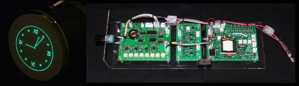
The Oscilloclock Core
An Oscilloclock Core, hand-crafted in 2015 for a discerning customer in GermanyThe standard Oscilloclock Core layout, on a test acrylic mounting
I supplied this particular unit with an 8SJ42J Chinese-made CRT, just for testing purposes. This is a 3″ PDA tube with a highly restrictive rectangular viewing area, but the customer found it just great for checking things out!
What comes with it?
Here’s what’s comprises the typical Oscilloclock Core:
1 x Fully assembled and programmed Control Board (optional on-board GPS)
1 x Fully assembled Deflection Board (latest ultra-linear revision)
1 x Fully assembled Power Board optimised for a given CRT (latest revision with options: onboard high-bandwidth blanking amplifier, rotation coil supply, auto fan speed control, unblanking plate modulation, and isolated bright/dim input)
1 x Fully assembled CRT Board (optional; an external blanking amplifier recommended when the CRT cable is longer than 50cm)
1 x Rotary encoder
1 x Worldwide 9V power supply (high quality wall wort unit, commercial ratings)
1 x Garmin GPS unit with 5m cable; wired to board-side connector (not required for onboard GPS)
1 x Set of standard inter-board and CRT harnesses for testing and reference (10kV/3kV silicone melt-proof used for HV cables, other LV cabling also heat-resistant)
1 x Cast acrylic test mounting assembly, fitted with the boards, ready for testing out-of-the-box with your CRT
1 x Ceramic adjustment screwdriver
Service documentation (schematics, board layouts, complete Digikey BOMs, harness specs)
All components are latest available types sourced within the last 6 months, 0.1% or 1% tolerance resistors, minimum 2 x rated working voltage capacitors, all lovingly hand-mounted by myself
All boards sprayed with HV lacquer for moisture and arcing protection
2-week satisfaction guarantee. But no long-term warranty on board-only purchases
Naturally, the lengths of all harnesses and inter-board cabling can be customized according to the owner’s requirements. And there is also an Oscilloclock Core Cube arrangement, where the boards are stacked to reduce the length and width of the overall unit.
What CRTs does it support?
The Power Board and Deflection Board are increasingly flexible with each revision, but I insist on performing all configuration of the Core here in my lab. This allows me to tweak for maximum performance, and provide a proper satisfaction guarantee.
Typically I work with the owner to recommend a CRT based on preferences such as size, colour, and aesthetics. However in cases where the owner already has a CRT in mind, and I don’t have the particular CRT or a close equivalent, I ask the owner to send me one to test against. Or, I simply procure one; after all, one can never have too many CRTs! (Though my better half does not agree…)
The current Oscilloclock Core board revisions meet the following operating parameters:
Maximum cathode to deflection voltage of 2175V
Maximum accelerator voltage of 3525V for PDA type CRTs
6.3V heater, max 0.7A
Support for “Deflection Blanking” CRTs (see treatise here)
CRT rotation coil supply (+/-5V)
Precision deflection amplifier capable of driving +/- 275V with 0.1% linearity
Like what you see?
Check out the Availability page for more information, and of course see the Gallery for some unique CRT creations – many with an Oscilloclock Core at their heart!
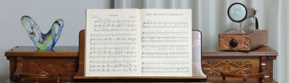
Happy New Year! Looking back, 2015 was a superb year, full of fun and fancy. And just in case you thought last year’s creative juices were exhausted by the fabulous Oscilloblock, rest assured that there was an even crazier creation – the 2015 luxury edition CopperClock!
The unusual facade for this unit was built to order by a Canadian craftsman specializing in hand-hammered and silver-soldered copper weather vanes. If you enjoy metal art, you will certainly approve of this!
But… you may have read my previous articles and know that three-inch Oscilloclock models are typically powered by 2.1kV high voltage power supplies. Isn’t there any danger in using a metal case?
Never fear! The internals are fully encapsulated in a beautiful cast acrylic case, providing full insulation and utmost safety.
Breaking from tradition, I’ll refrain from describing other features of this unit (such as the selection of a round-faced CRT to give it character), and instead just post a few more photos of the clock ‘in situ’. Enjoy!
The 2015 CopperClock atop a beautiful Philips Radioplayer. What a match!… or perhaps atop a vintage Estey pump organ?… perhaps it looks best on a 1920’s Edison Diamond Disc Phonograph!
Like what you see?
This exquisite specimen is currently available to someone with a metallurgical and chronometric disadvantage. Visit the Availability page for more information, and of course see the Gallery for other unique creations!
Fresh off the press – some photos of the Oscilloblock – Summer Dusk edition in its new home! The owner is clearly a huge Nixie tube and neon aficionado, but this is his very first CRT clock. What a fitting environment!
Ahh, summer – it’s well and truly over. But one person in the world is able to enjoy the warm, cheery feeling of summer every single day: the proud new owner of this beautiful Oscilloblock – Summer Dusk edition!
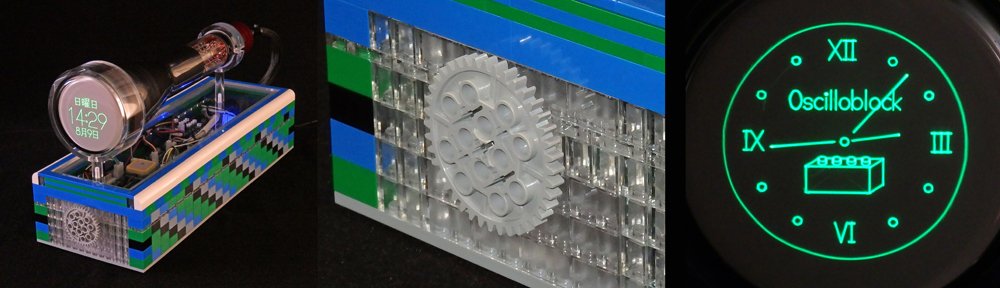
Truly the best thing to come out of the lab this summer – the Oscilloblock!
The Exterior
This playful timepiece features a Lego art case, painstakingly designed and constructed by Oscilloclock lab’s junior technician from a whopping 548 brand-new Lego parts sourced from around the globe. No expenses spared! Even the control knob is actually a Lego Technics gear. And just in case the owner wanted to take it apart and build it all over again, we included a 140-step Lego building guide in the package. Good luck!
The Oscilloblock features a good-looking 1970’s 3-inch (75mm) flat-faced CRT from Toshiba, with the iconic scripted logo in great condition on the base. At the rear is a scarce brown bakelite CRT socket, which are very hard to find complete with the rear insulating cap! The harness consists of tough 3kV tolerant silicone-sheathed cabling, shielded over most of its length to reduce electromagnetic interference.
Wow, these vintage bakelite CRT sockets are hard to find!No doubts about authenticity!
One design goal was to have more than 90% of the CRT’s surface area completely exposed for viewing and touching, as opposed to encasing it in acrylic. Borne from this was a tremendous achievement for 2015: a new CRT ring support structure!
Acrylic rings with super-tiny pocket holes… cast and machined in Japan!
Internals
The internals of the clock are equally exquisite. A set of latest-revision Oscilloclock control, deflection and power boards drive the CRT at 2.1kV, providing a crystal-clear, ultra-bright trace. And of couse, every figure and character is generated using silky-smooth Circle Graphics.
The CRT assembly simply lifts away for showing off the internals! But DON’T TOUCH…Latest-revision boards. 250+ components. All hand-mounted!On-board GPS for accurate timing – anywhere in the world!
Operation
There is only one control. It’s intuitive. It’s fun. It’s simple! Visit my YouTube channel to see various Oscilloclocks in operation.
But not everything is obvious, and Oscilloclocks all ship with an Operation Guide, with content specific to each and every unique unit. Here’s a snippet from the Oscilloblock’s guide:
No Oscilloclock model ships without a decent Operation Guide!
Like what you see?
There’s really no limit to what can be done with a CRT and an idea! It was my son’s idea to use Lego, and he is proud to know there is nothing in the world quite like this Oscilloblock. See the Gallery for other equally unique creations.