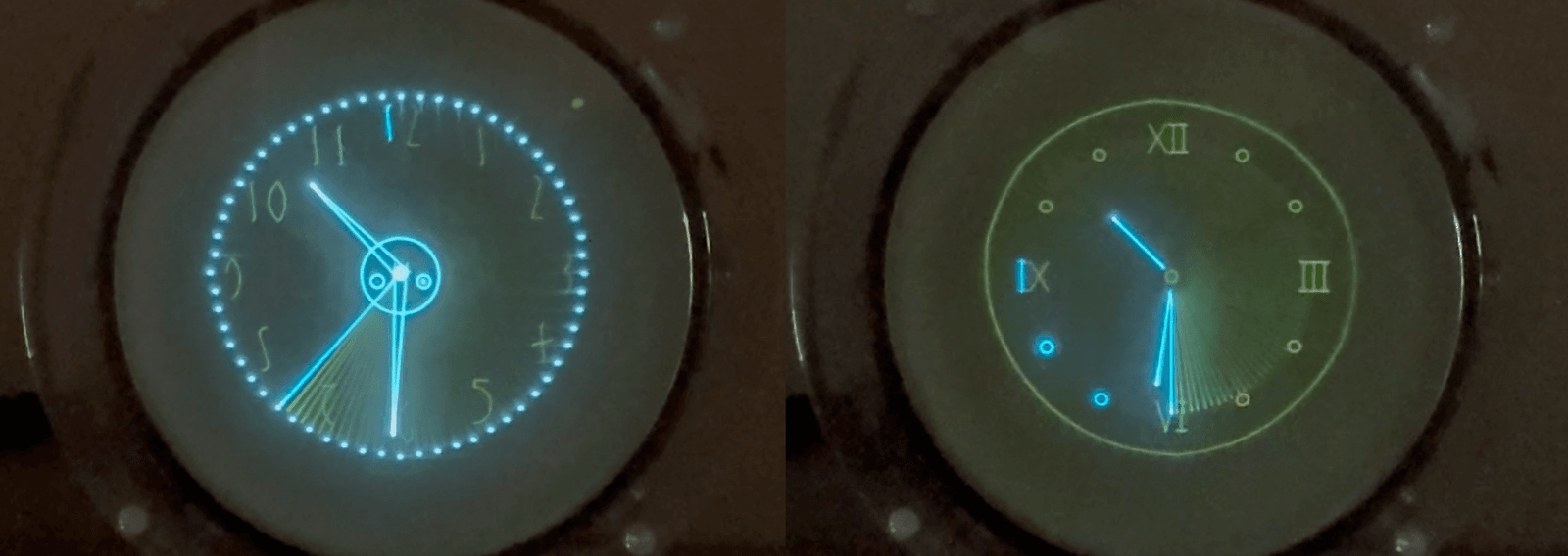
No! We’re not here to talk about a new Star Wars character! The 3KP1 is a type of cathode-ray tube that was used in many low-cost 1960s-1970s Japanese oscilloscopes.
And the Exo is a series in our Oscilloclock range that fully exposes the CRT both visually and physically, much to the delight of the owner and visitors – while of course protecting high voltage areas from dust and prying fingers.
The Exo 3KP1!
First crafted for [Jerry] back in 2019, the Oscilloclock Exo 3KP1 is the default character in the Exo series, alongside the arguably oddball Oscilloblock – Summer Dusk Edition and the slightly more exotic OscilloTerm Exo B7S4.
There’s nothing more soothing than the green glow of flourescent phosphor backed by the amber ambience of the CRT heater. Ahhh, that’s nice.
This Exo shipped with all the “standard” screens, like the analog clock face below. But why stop there? We’ve done custom logos, movie themed features, oddball time systems, and so much more!
From the top, [Jerry] and his dinner guests can readily inspect every square centimeter of the CRT and its exquisite innards. Cooool.
Inside the unit, neatly tied cabling lends an air of gentle sophistication, while the green of the circuit boards harmonizes well with the phosphor.
Even as a baseline model in the series, the Exo 3KP1 is distinctly attractive.
[Jerry] did make some choices along the way, including which CRT to use. Let’s explore his CRT options in more detail!
Round vs. flat
The flat-faced 3KP1(F) version
As shown in the photos, the CRT that [Jerry] selected has a slightly convex face. This was the standard shape of the original 3KP1 type CRT, and is a perfect choice for the Exo case style, as it visually softens the glass edge exposed in front of the acrylic ring supports.
The round-faced 3KP1 was superseded after some years on the market, by a flat-faced version: the 3KP1(F). This version is rather more commonly found and they are delightful to use. We used a 3KP1(F) in the Exo series Oscilloblock, as shown at right.
Which would YOU prefer – round or flat?
Phosphors and flavours
[Jerry] had another choice to make: the phosphor! While the standard phosphor of most CRTs of the day was green, other colours were available such as amber, blue, white, purple. Such CRTs are more rare, but we have some… and so could Jerry!
Phosphor diversity. What would [Jerry] go for?The “trailing effect” on a long-persistence CRT
There were also varieties of CRT with different persistences; i.e., how long the trace would continue to show on the screen! We love this shot of the moving second hand on a blue, long-persistence CRT:
And, we just happened to have a 3KP7 CRT in stock with exactly these characteristics.
But in the end, [Jerry] wanted the nostalgic look of an old green-screen computer monitor, and chose the stock-standard 3KP1.
Nice choice!!
The longevity question
[Jerry]’s clock shipped with a used 3KP1 CRT. Pre-owned, pre-loved, and pre-21st century.
But we don’t sell junk. [Jerry]’s CRT was selected for its unblemished phosphor, and for its still-bright and vibrant performance. And, of course, there is the standard warranty of 1 month for a used CRT:
But the question often comes: “How long will a CRT really last?”
Here at Oscilloclock we don’t mince words, and we don’t use euphemisms (much!). But the fact is this – after 15 years of crafting Oscilloclocks for customers around the globe, no-one has reported having to change their CRT. Maybe it’s happened and we are oblivious. Even better!
Our secrets to CRT longevity are:
We select only the highest quality CRTs, made by reputable manufacturers. [Jerry]’s CRT was manufactured by Toshiba, a key supplier of the day.
We check CRT specifications carefully, and avoid those with any hint of short lifetimes. (Some CRTs had very short expectancies, such as 1000 hours! Perhaps these were used for demanding applications where even a tiny degradation in performance could not be accepted.)
Oscilloclocks employ a soft-start mechanism to minimize stress on the CRT heater.
The Spare
Notwithstanding our facts around longevity, [Jerry] decided to plan ahead for an eventual CRT replacement. He purchased a stunning new-old-stock Hitachi 3KP1, with quality certificate and even in its original box.
They don’t get more original than this!
But is a Hitachi 3KP1 better than a Toshiba 3KP1?
We’ve compared them, and couldn’t tell any difference in performance or characteristics. We did notice one thing, though: the Hitachi is significantly heavier than the Toshiba. Hmmm….
One day, we’ll dissect some (defunct) units, and get to the bottom of that odd observation. Stay tuned for a post!
Like what you see? [Jerry] did. Check out our other creations!
Some time ago, [javadesigner] asked something that no doubt many of you have been wondering: Do Oscilloclocks emit radiation?
Had a question about oscilloscopes – specifically cathode-ray tubes (CRTs). X-rays etc were discovered in similar tubes, and I’ve read that high kV tubes produce both beta and X-ray radiation.
… Have you ever measured x-ray emissivity with CRTs, and if so, are there any mitigation strategies – especially for X-rays? Leaded glass enclosures, etc.?
Great question!
Will your faithful Oscilloclock do this to you? CRT used in this demo: 130BFB31
Fortunately the answer is a clear NO. Our hand-crafted Oscilloclocks do not emit dangerous radiation.
The general rule of thumb with CRTs (in fact, any electrical equipment operated in a vacuum) is that X-ray emission is negligible at anode voltages less than around 10kV. The accelerated electron beam simple does not have enough energy to generate X-rays when striking the phosphor screen.
But above 10kV, X-rays can and are produced as a result of the higher-energy bombardment. The high-voltage CRTs used in television and computer monitors of the day always incorporated lead glass (strontium-barium glass), to block these X-rays. (And… to protect against implosion!)
In any case, all Oscilloclocks operate at voltages well below 10kV, so this does not become an issue.
Just a few of our CRTs in stock – and none of them emit X-rays!
Thats right – whether we craft your custom timepiece from a behemoth 6498 (at left, operating at 6 kilovolts), a delightful D4P (3kV), a sleek 3WP1 (1.5kV), a cute 50SB1 (1kV) or an eentsy-weentsy CV2302 (500V), you’ll be illuminated but never irradiated.
Fascinated by electron beams and phosphor bombardment? Do you have a question that everyone else wants to ask? Query away, we love Q&A!
The long-standing favourite amongst Oscilloclock aficionados is the External GPS (Garmin ‘puck’) option. Features include:
a long cable that allows positioning for best sensitivity
an inbuilt magnet for attaching to metal beams
a gorgeous connection system – satisfying haptics and robust locking
Of course, we also have the internal GPS option, where the GPS receiver is mounted on the Control Board itself. This is super nifty, if there is no concern about satellite signal strength where the clock is placed. (This is very rarely an issue. These receivers are extremely sensitive!)
Can you spot the onboard GPS module in this gorgeous OscilloBlock?
Geolocation
The GPS option allows the Oscilloclock to obtain not just time, but also geolocation information from satellites.
Okay, it’s true that Oscilloclocks are generally placed in a fixed location, so showing the clock’s location on a map might not be very useful…
Think again!
How about an OscilloGlobe, to warm up your long-distance relationship? Plot you and your friend’s Oscilloclocks on a spinning globe, and count down the hours til you meet again…
A delightful Heathkit SB-610 shows another Oscilloclock, live and ticking elsewhere in the world! (Want a closeup of this demo feature? See this video)
Or perhaps you fancy an OscilloWear? A wearable Oscilloclock, sporting a miniature CRT and it’s-only-possible-in-Japan miniaturised circuitry! Complete with GPS.
An OscilloWatch capable of recording your sporting activities? With OscilloMaps that guide you to the nearest Oscilloclock retailer? And of course: the OscilloPhone, or oPhone for short?
Ahh, we could have so much fun making devices that use location data…!
Want even more info on the GPS hardware option? We have a nice support page here: Garmin 18x GPS Puck.
NTP – low-cost & extensible
The Oscilloclock Wave is the glorious device that allows your Oscilloclock to connect to a Wi-Fi router and pull in time from NTP (Network Time Protocol) servers.
It comes in different forms, both external and internal:
WaveWave Onboard
Wave Core
The Oscilloclock Wave requires a WiFi connection (and Internet), and some initial configuration – it doesn’t just work straight out of the box, in a standalone way like the GPS option.
However, the Wave has a distinct advantage: it can access various APIs (think: providers of data over the Internet) to pull in and display all kinds of information!
To date, we’ve used this capability in several themed Oscilloclocks: the Astro Clock (pulling in sidereal time from an API) and the AfterShock Clock (pulling in earthquake data).
Sidereal time, for all the astronomers out there!Earthquakes are disasters – no joke. But a semi-live visualization in Lissajous figures? Too cool..
Not saturated yet? For more on Wifi based synchronisation and various configuration options, see the support page: Oscilloclock Wave.
The No Synchronization option!
Do you want to take your Oscilloclock off-grid? We’ll craft you a unique clock powered by wind, solar, USB-C power bank, or even a hamster wheel. (We can even procure extremely low-power CRTs!) But to go fully off-grid, you won’t want to use GPS or WiFi.
A (more likely!) scenario is simply that signal strength is just too poor. Maybe your clock sits in a basement 3 stories below ground…
For such cases, you can set the time manually in the Time Setting screen. Once set, an on-board quartz oscillator then maintains reasonably good time (in the order of seconds per month). You’ll want to adjust it occasionally!
Must it be one OR the other? Can’t a gadget lover have their Oscilloclock source data of different types from both GPS and public APIs over the Internet?
Sadly, no – not in the current Control Board revision. This supports only a single interface, which is occupied by either the GPS or the Wave module. (We have multiple input capability on the long to-do list!)
Oscilloclocks are beautiful and entertaining. There’s that warmth of the CRT filament and the brilliance of coloured phosphor excitation, combined with all the features of our digital era.
But above all – they are clocks! Hope you enjoyed this treatise on how time is managed.
If you’re up for the craziness of an Atomic Oscilloclock, or if you want a custom theme using specific API data, let me know! Otherwise, stay tuned!
Here at the Oscilloclock lab there’s nothing more pleasurable than helping put a cherished vintage oscilloscope back into action. A new lease on life!
That’s why when [Chris] reached out about his early 1970’s Conar 255 oscilloscope, wanting to convert it into a Vectrex gaming machine, we were naturally excited!
The original Vectrex was an incredibly cool device. Instead of the pixelated, blocky graphics of the time (anyone remember Pac-Man?), the system used vector graphics to draw smooth line-art images. Each vector was a straight line, or a smooth arc, connecting point A to B. Vectrex games were true works of art, and the original hardware is quite rare (and $$$)!
Well, [Chris] caught the vector graphics bug. But he decided to build a Scopetrex – a hardware emulator that allows you to run Vectrex games on an oscilloscope! He would theoretically just connect this to the Conar 255’s existing X, Y, and Z (blanking) inputs.
We like this “minimum invasion, maximum re-use” approach. We’ve gone down this route numerous times to craft Oscilloclocks out of still-usable hardware. (The alternative? Install a full set of modern boards that drive the CRT directly.)
Sample specimens of “minimum invasion, maximum re-use”
[Chris] got down to planning. He could interface the X and Y inputs easily. But he faced a problem with the Z (blanking, or intensity modulation) signal, which instructs the scope when to turn the beam on and off:
The Scopetrex outputs a 5V DCdigitalblanking pulse.
The Conar requires at least 20V peak-to-peak blanking signal – and employs analog AC coupling.
We’ve solved this mismatch problem before using various non-standard Oscilloclock board setups and complex hook-ins to the existing circuits. Always on a case-by-case basis, always unique.
But now, at last, it was time to standardise the process. To make it easy. To adapt any vintage oscilloscope for digital blanking from a microcontroller! We proudly announce the next member of the Core family: The Z Core!
The Z Core (in this case, a Z Core 2 Ex) …
… joins the Oscilloclock Core family!
How to install it
Believe it or not, the minimal installation requires just 3 steps. For almost any oscilloscope! The Z Core effectively sits in series between your device’s blanking supply and the CRT grid.
Snip the wire connecting to CRT grid.
Connect the orange wire from the Z Core to the circuit side of the cut wire.
Connect the green/yellow wire to the CRT grid.
Snip.Connect!
Visit the Z Core Support Page for lots more detail, including the obligatory warnings about high voltage. There are also details on how to connect the Z Core to your controller, detailed specifications, and some fun Q&A to help answer your most burning questions!
The Z Core 2 Ex!
We’ve wanted to develop a dedicated, built-for-purpose Z Core product for a very long time. This would consist of a single, miniaturised, low-power board called (ingeniously) a “Z Core Board”, and a few harnesses.
But [Chris] didn’t want to wait for Oscilloclock labs to work through its ever-growing bucket list. Could we deliver within 2024?
Yes!
In past retrofits such as the Kikusui 537, we’ve taken spare boards that were originally designed for fully-featured Oscilloclocks, and partially populated them with only the necessary components to serve the blanking purpose.
Partially populated Oscilloclock Power Board
For [Chris], we found an almost fully-populated new-old-stock Power Board v2.27 and compatible CRT Board v1.21 lying around, just dying to be used and loved by someone. Older revision boards do tend to be set aside, as folks want the latest and greatest.
With just a few minor modifications, this assembly shipped – and is now branded as the Z Core 2 Ex. The “2” refers to the Power Board’s major revision, and the “Ex” stands for “external blanking amplifier” (the function of the CRT Board). The Power Board rev2.2x series boasts an on-board blanking amplifier, but this section wasn’t already populated. What a great opportunity to use up a stock CRT Board!
[Chris] will be happy. And we’ll keep up this spirit of minimising waste. You’ll see some other Z Core assemblies popping up in future: a Z Core 1 Ex, a Z Core 2, and potential variations of Z Core 3’s.
And finally, one day, a genuine dedicated Z Core will be born!
Why your scope needs a Z Core …
Many old oscilloscopes simply don’t have any input for Z blanking, Z axis, intensity modulation, or cathode modulation. (Look carefully – it goes by many names!) Or, the input may be there, but it’s not compatible with a microcontroller. Why couldn’t the designers offer a decent interface?
Well, it all has to do with high voltage! To get there, let’s cover how CRTs work in just three short sections:
Gun
A cathode-ray tube (CRT) has an electron gun that shoots electrons at the phosphor molecules on the screen. The electron beam is deflected by putting positive and negative voltages into electrodes placed in the CRT’s neck, and this is how patterns are drawn on the screen.
This is how a CRT works. It’s awesome.
But the electron beam has to be turned on and off, to break the pattern and make meaningful images on screen. This is known as blanking.
Blanking
Oscilloscopes, particularly, have to blank the beam when it goes back (retrace), from the right to the left again. If there were no blanking, you’d see a retrace line – wickedly cool for us artists, but devastatingly distracting for engineers who want to focus on the waveform itself!
Retrace lines – arty but not desirable
Oscilloclocks also rely on blanking. In Circle Graphics, where all figures are composed of lines and circles, blanking is crucial to creating meaningful segments. For example, a “C” is readily created from an ellipse “O”, simply by blanking the beam at just the right place!
A blanking pulse kills the beam to get a ‘C’
Grid
CRTs are designed for blanking. There’s a valve-like electrode called a grid that sits inside the gun, just in front of the cathode where the electrons are spat out. If you inject a negative voltage into the grid (compared to the cathode), it repels those electron babies and sends them back where they came from. They don’t bombard the screen, and no more light is emitted. Blanking in action!
Titillating! Electron field density is reduced when a negative voltage is applied to the grid!
A fuller explanation – from The Bible
The bible
A change in grid voltage influences the field distribution of the first lens, and in so doing controls the emission from the cathode. For any fixed value of voltage applied to anode 1, it influences the number of electrons which pass through the cross-over point. Let us see how this comes about. In Fig. 5-17 is shown the field distribution in the first lens for two values of grid bias, O and -30 volts, and a fixed value of voltage on the plate.? It is clearly evident that with zero bias, the area adjacent to the cathode, between the cathode and the control-grid aperture, has a comparatively high positive potential as the consequence of the field between the control grid and the first anode. Under such conditions of zero grid voltage, it has been found that the area of the cathode which is emitting corresponds approximately to a projection of the area of the grid aperture; the maximum number of electrons are passing through the grid opening and the beam-current density is high.
When the control grid is made negative by an increase in the bias, —30 volts in the illustration, the field distribution in the vicinity of the cathode is altered so that only the center of the emitting surface is behaving as an emitter. The other areas are influenced by the space charge and effectively are not emitting. The result is a reduction in beam density and several other related effects.
High voltage
So – back to the high voltage aspect. The cathode and grid are usually about 2kV (that’s right – 2,000 volts!) negative compared to the rest of the circuits. If you connected an external input signal directly to the grid, something would fry.
Old-school oscilloscope designers took a very easy (read: cheap) solution: they stuck a high voltage capacitor between the grid (or cathode) and the external signal. This is called AC coupling because the capacitor blocks the DC voltage (2kV), and only couples through the AC (the fluctuating blanking) component of the signal.
AC coupled external intensity modulation in the Conar 255 (L) and the Trio CS-1554 (R)
This method of intensity modulation was fine for the regular, repeating signals observed in old TVs and radios. But it isn’t what [Chris], or so many millions out there like him, needs! They need to send through an irregular, sometimes not-fluctuating-at-all (i.e., DC) signal. They need DC coupling! And it has to be isolated – standing off more than 2kV!
And there’s another voltage related problem: the grid has to go substantially negative with respect to the cathode, in order to completely block the electron flow. We’re talking 20-50V typically. This is not a voltage that a modern microcontroller board will deliver! This requires an amplifier.
Summing it up
So that’s it! Just three(?) words. We need an isolated DC-coupled amplifier. And it needs 2kV isolation with a 10x amplification factor.
Welcome to the Z Core!
Demo
No assembly can leave our lab without being fully tested, and without a demonstration to ensure the customer’s utmost satisfaction. Here’s how the demo went:
The host device: Trio CS-1554
This venerable Trio (also branded as Kenwood) hails from around the same era as the Conar 255. It was attractive, had fairly good specifications, and a low(-ish) price tag, making it very popular both in Japan and overseas. Documentation is freely available and… more importantly, I had one lying around!
Look carefully – it’s bulging and leaking!
Of course this device is full of high voltage oil capacitors. These were effective in their day, but they break down over time, and things get very nasty. One particular HV capacitor in this unit was overheating to the point that the metal case had warped, and oil was even leaking out! Ick.
A few modern-day capacitors hacked together replaced the leaky unit and saved the day. Onwards!
Connect Z Core outputs to Trio CRT grid and grid circuit (as shown in earlier section)
Incompatibility! The Trio’s horizontal input seemed to want 10V peak-to-peak for maximum deflection (this is way off its original specs of 250mV/cm. I think it’s broken!) The Connect by default has only a 3V peak-to-peak output signal. The image is going to be small… ↩︎
Trickery! The Connect by default is designed for a display device with a high-impedance Z input. The Z Core 2 Ex has a low-impedance input and 15mA drain at 5V. A temporary mod was needed in the Connect – which was promptly reversed after the test. ↩︎
The result? A relatively clean image, albeit small! But the blanking works well. [Chris] was okay with the jagged edges and other blemishes; these are attributable to the Trio’s rough condition.
Performance testing
The Oscilloclock cave is not a precision testing laboratory. But we do have a significant collection of equipment, and every piece plays its part. In this case, we deployed a Hewlett Packard 1901A Pulse Generator.
Choosing amongst a plethora of delightful old oscilloscopes, we stayed with the HP theme and used a venerable but still digital HP54615B.
Set output to 5V and connect to the Z Core’s input
Connect a 20pF capacitor across the Z Core’s output, via the standard 200mm 22AWG harness
Connect Ch1 of the scope to the input, Ch2 of the scope to the output
Results
Measurement
Assembly: Z Core 2 Ex
Waveform base voltage
-46V
Rise time
130 ±10 ns
Fall time
180 ±10 ns
Propagation delay
120 ±10 ns
Effective bandwidth
DC to 3 MHz (limited by rise/fall time)
These results were satisfactory. But at some point, we’ll try the same with a Z Core 1 and a Z Core 3. And one day – a purpose-built pure Z Core. Stay tuned!
In conclusion
Well, that’s a wrap! The tested assembly has now shipped, and soon [Chris] will be able to try out a Scopetrex on his minimally-modified Conar oscilloscope. Fingers crossed!
For more technical info, fun facts and Q&A, check out the Z Core Support page. And for a peek at our range of gadgets, be sure to check out the Gallery.
Here’s a rare thing: Take the Toshiba ST-1612B Oscilloclock. Run the OscilloTerm VT52 terminal feature. Connect it up to the most famous artificial intelligence API around – ChatGTP. And what do you get? OscilloChat!
Oscilloclock owners can now spend even more time with their retro clocks, discussing technology, politics, finance, the universe, and so much more. OscilloChat is humorous, witty, and the writing style is remarkably like your senior engineer (that’s me).
At best, this is eerily entertaining. At worst, it’s annoying and entirely untrustworthy! Let’s see what happened when I asked: “What’s your favourite Oscilloclock?”
To see this and more incredible videos in high resolution, check out Oscilloclock on YouTube!
They don’t call it generative AI for nothing. Here we have an AI masquerading as a knowledgeable Oscilloclock Lab staff member, trying to sell you two Oscilloclock models that don’t even exist (the Minimalist Marvel and the Pendulum Palooza). And when challenged with “Is it real?” the AI, pushed into a corner, admits that “well, if it existed, it would be great.” It’s like dealing with a child.
The fictitious “Pendulum Palooza” Oscilloclock
But like we do with children, let’s give OscilloChat a chance! Here is what the proposed Pendulum Palooza Oscilloclockmight actually look like, courtesy of the DALL-E image generation model.
Dear readers, please draw your own conclusions!
How it works
The OscilloChat experiment setup is simple. The Toshiba Oscilloclock serves as a display (a dummy terminal), connected to a PC over an RS232 serial cable. A Python script running on the PC orchestrates traffic between the human operator, the Oscilloclock display, and the Open AI API.
Interaction with the GPT AI
The Python script first creates a session with the GPT AI. It then sends an instruction telling the AI what it is; i.e., to give it a role, including any specific instructions that it needs to follow in the subsequent conversation with the human:
"You are an assistant at Oscilloclock.com. You will be asked questions about any topic. Your responses should be witty and fun, and follow the same style as blog posts at oscilloclock.com web site. Responses should be short (within 512 characters). You can ONLY use ASCII characters! Do NOT use non-ASCII punctuation marks. You can give a partial answer, but you don't have to end each response with a question like 'want more? just ask!'"
Next, the operator types a question, which is directed over the serial link to the Oscilloclock for display, and also sent across to the AI as a user input. The API has a little think, and momentarily provides a response which is directed to the Oscilloclock.
Until the session is closed (e.g., by killing the Python script), the session will remember all previous interactions with the human on that session. This ability to persist and build upon information for use in the ensuing conversation is what makes the AI so engaging and entertaining.
Delay effects
Each response back from the AI is sent character by character to the Oscilloclock display over the serial link. But even at 9600 baud (a turtle’s pace, by any modern standard!), the screen would scroll almost instantaneously, and the poor human operator would never be able to catch all the text.
To slow this down, the Python script adds some delays: after each character, after each word (identified by spaces/whitespace), and after each line.
Besides making things easy for the operator, it also gives a neat impression that the AI is thinking while composing its replies!
Lissajous Watermark
Plain character displays can get boring. Happily, Oscilloclock Lab has a solution for every kind of ‘boring’! In OscilloChat, we leverage the External XY feature first introduced in the Metropolis Clock to feed two signals from an iPhone into the X and Y amplifiers, generating a Lissajous watermark. What a way to make a dumb terminal display look smart!
Dissecting the dribble
If you want to dissect OscilloChat’s dreadful dribble in detail, here’s the full transcript:
Hi, tell me about yourself!
Ochat: Well hello there! Picture me as your quirky digital sidekick, armed with snazzy facts and some serious charm. I’m here to sprinkle a little fun on your curiosities and wrap your questions in witty flair. Think of me as the zany clock in your atticalways (sic1) ticking, forever colorful, and here to help you find the right time for any topic! So, what tickles your fancy today?
What is your favorite oscilloclock?
Ah, the grand question of favorites! While I can’t cozy up to a specific oscilloclock like a warm cup of cocoa, each one boasts its (sic2) unique charmlike (sic3) a carnival of timepieces! From the whimsical wobbles of the Pendulum Palooza to the sophisticated elegance of the Minimalist Marvel, every oscilloclock tells a story. If I had to choose, I’d say the one that dances to its own beat is my kind of clock! Ready to find your oscilloclock soulmate?
Tell me more about the Pendulum Palloooza (sic) Oscilloclock… is it real?
Ah, the Pendulum Palooza Oscilloclock(sic4) it sounds like a time-traveling festival, doesn’t it? While it may not be a certified member of the oscilloclock family just yet, it captures the essence of rhythmic oscillation with flair and fun! Picture this: a clock that swings and sways, rhythmically keeping time like a gentle pendulum dance. If only it existedwho (sic5) wouldn’t want to host a party where every tick-tock brought a new groove? Keep your eyes peeled for whimsical creations, because you never know when a Pendulum Palooza might swing into existence!
Nice! thanks for the feedback
Anytime, time traveler! I’m always here to sprinkle some fun on your quest for knowledge. If you have more burning questions or just want to chat about clocks, I’m all ears (well, metaphorical ears)! Keep ticking and tocking along with curiosity!
Missing dash (technically an em dash, Unicode U+2014). This should read “… attic — always …” ↩︎
Missing dash. This should read “… charm — like …” ↩︎
Missing dash. This should read “… Oscilloclock — it ….” ↩︎
Missing dash. This should read “… existed — who …” ↩︎
You can see from the footnotes that the AI is responding with non-ASCII characters. These cannot be displayed (yet!) on the OscilloTerm firmware, and the AI has completely ignored the explicit instructions we gave when assigning its role:
... You can ONLY use ASCII characters! Do NOT use non-ASCII punctuation marks. ...
But scolding the AI about this results in a childish non-apology, and quick change of subject:
You were NOT supposed to use any non-ASCII characters, like dashes or right quotation marks!
OChat: Oops! It looks like I got a bit carried away. No special characters from now on, I promise. Just plain ASCII fun ahead! What can I help you with today?
(Note: this interaction was not included in the video.)
What’s Next?
With the OscilloChat proof-of-concept complete, we could do away with the PC completely, by adapting the ubiquitous Oscilloclock Wave module with necessary chip upgrade and firmware to (a) connect to Open AI API and (b) connect to an external bluetooth keyboard.
Taking a step further, we could do an OscilloChat2 (OscilloChat Squared) where two OscilloChats interact with each other. What would the conversation be like? Where would it lead?
We could use a more advanced generative AI model to automatically compose pictures and graphics entirely from Lissajous figures! (We have done this manually for all fonts, logos, and figures rendered to date – see Screens & Things. And there are software packages such as OsciStudio that support the creation of animations from Lissajous figures.)
Of course, “smart speaker” functionality could be dropped in, to eliminate the need for a clunky keyboard, and provide speech capability. OscilloChat could become OscilloChatty! How cool? How annoying? You be the judge!
All excellent items to add to the ever-growing list…
Credits
[Eric], the protagonist of the recently published Zork on an OscilloTerm!, noticed this at the end of the post:
He just couldn’t help pick up the gauntlet! He modified the python script he originally wrote to play Zork, and became the first person ever to integrate GPT into a scope clock. Check out his own video of Zork and GPT running on his OscilloTerm!
Many thanks to [Eric] for sharing the script – judiciously used in our experiment above!
Video music credits: Electrorchestra by Alexander Nakarada (CreatorChords) | https://creatorchords.com Music promoted by https://www.free-stock-music.com Creative Commons / Attribution 4.0 International (CC BY 4.0) https://creativecommons.org/licenses/by/4.0/
Like what you see? Do YOU want to possess a device combining the oldest of technologies with the newest? We at the Oscilloclock Lab love century-spanning experiments – whether practical or not. Stay tuned for more!